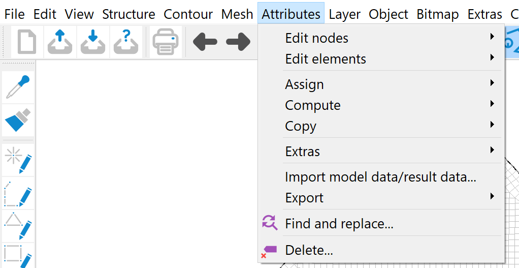
The attributes menu can only be selected in model file mode. The following menu items are available:
Edit node
After using Pick…, Number… or selecting with the Edit node button ( ) in the toolbar, the following input window appears in which the attributes of the node can be edited:
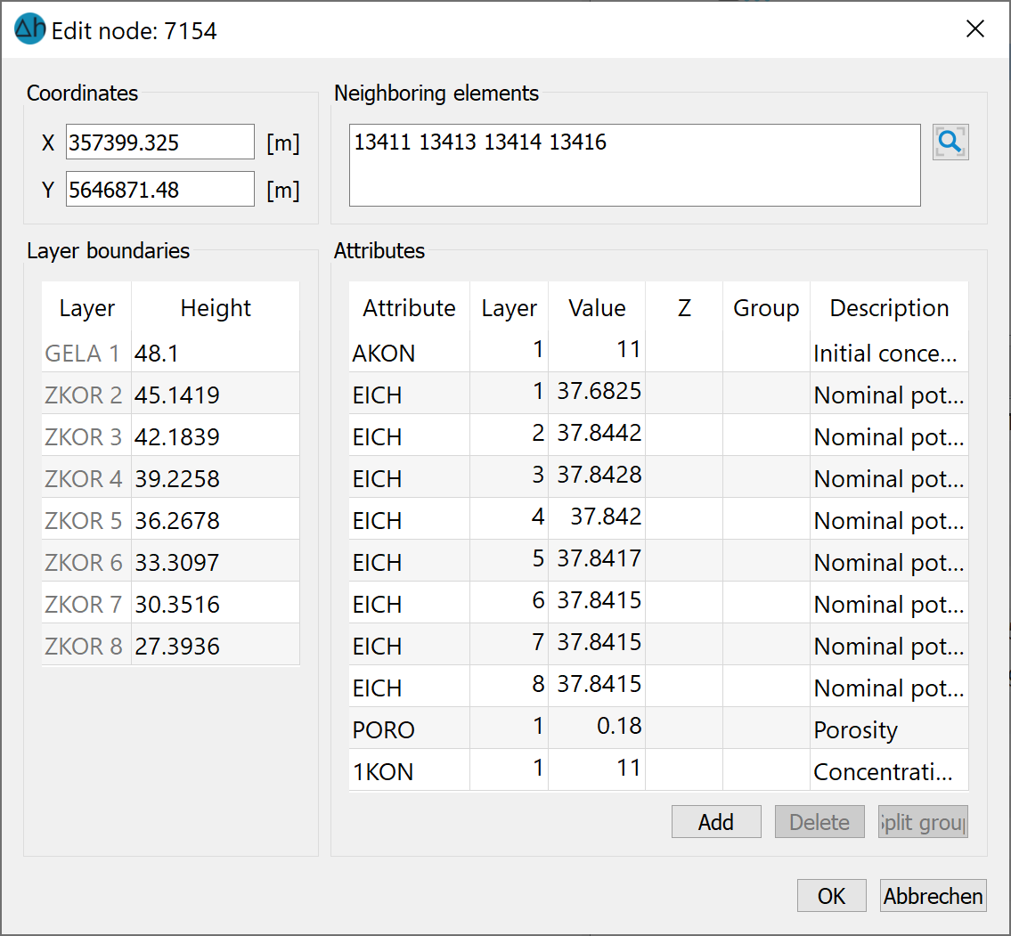
Coordinates:
The x and y coordinates of the node can be changed directly here. However, care must be taken to ensure that the node is not moved into other elements by changing the coordinates. When moving the node by changing the coordinates, the node attributes remain unchanged.
Neighbouring elements:
The element numbers of the elements neighbouring the node are displayed here. By activating the magnifying glass button ( ), the graphic display is zoomed to the selected node.
Layer boundaries:
The geometric data is displayed here, e.g. the terrain surface as the upper layer boundary or, in the case of a 3D model, the position heights of the Z coordinates.
Attributes:
Here, attributes of the node can be added (left button), deleted (right button) or changed via manual input in the cells of the table (Value, Group or attribute character (Z)). After opening the model, the node attributes are not yet loaded. Only by marking the attribute to be edited and then clicking on the "Load" button are the associated node values read from the model file and can then be edited. All node attributes in the model file are displayed first. If a selected attribute does not exist at this node, this entry disappears after clicking the "Load" button..
Split group:
If the node has a group attribute such as LERA or MARK, the "Split group" button is activated after selecting the corresponding attribute and the attribute group is split at the subsequent node. The subsequent node results from the original assignment direction. A new group is then automatically created for the following nodes.
If the menu is closed with OK, all modifications made to the node data take effect. However, the change can be cancelled with the Undo ( ) button.
If the menu is closed with Cancel, all changes made are cancelled: the node data remains in the state it was in before the menu was called up.
Edit element
After using Pick…, Number… or by selecting the Edit element button ( ) in the toolbar, the following input window appears in which the attributes of the element can be modified:
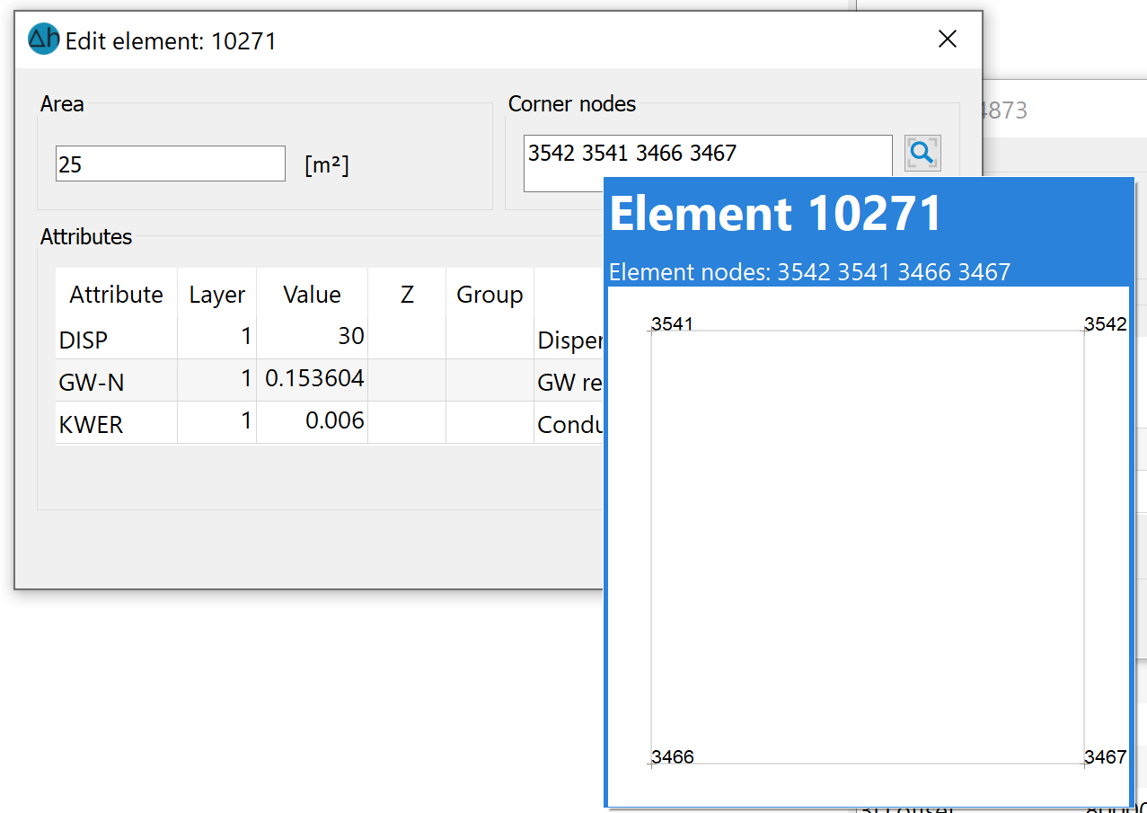
Corner nodes:
The node numbers of the corner nodes of the element can be found here. When hovering over the corner nodes with the mouse, the geometric arrangement of the nodes on the element is also displayed. When activating the magnifying glass button (), the button zooms the display to the selected element.
Attributes:
Here, attributes of the element can be added (left button), deleted (right button) or changed by manual input in the cells of the table (Value, Group or attribute character (Z)). After opening the model, the element attributes are not yet loaded. Only by selecting the attribute to be edited and then clicking the "Load" button are the associated element values read from the model file and can then be edited. All element attributes in the model file are displayed first. If a selected attribute does not exist for this element, this entry disappears after clicking the "Import" button.
If the menu is closed with OK, all modifications made to the element data take effect. However, the changes can be cancelled with the Undo button ().
If the menu is closed with Cancel, all changes made are discarded without saving: the element data remains in the state it was in before the menu was called up.
Assign
As this menu sub-item is very complex, it is dealt with in a separate sub-chapter.
Compute
As this menu sub-item is very complex, it is dealt with in a separate sub-chapter.
Copy
As this menu sub-item is very complex, it is dealt with in a separate sub-chapter.
Extras
The following submenu appears:
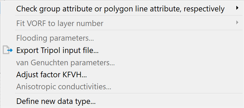
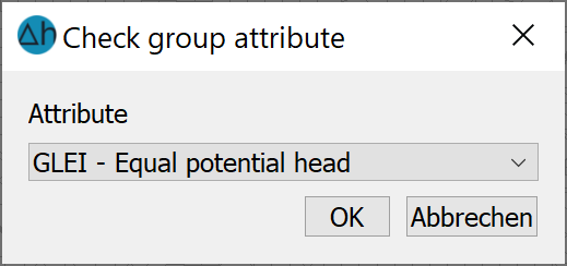
Check group attribute or polygon line attribute, respectively
This menu item can be used to check existing attributes (individual, all or isolated line attributes) with group data or polygon line data for overlaps with similar attributes.
A single attribute input window is displayed:
The group or polygon line data with overlaps are displayed as green lines. The nodes on which attributes are defined twice are highlighted with green circles.
These nodes are captured using the Attributes  Edit nodes Pick… menu item and the corresponding groups can be selected for deletion in the dialogue that appears.
Fit VORF to layer number
This menu item can only be selected if it is a 3D model and the attribute VORF (reference water level (stage) for watercourses) is assigned. Two selection options are available in the submenu.
Fit VORF to layer number:
This approach is ideal for watercourse datasets that describe watercourses near the surface.
Even with fine vertical discretisation of a 3D model, the exact terrain slope on a receiving watercourse is often not sufficiently discretised. It is thus usually the case that the mesh node on the receiving watercourse “hangs” in the uppermost layers in the air, i.e. above the water level (see figure below). In such cases, it makes sense to set these nodes to the same height so that the leakage boundary condition takes effect at the correct point.
The easiest way to do this is to assign the VORF attribute and the corresponding leakage coefficient (LERA or LEKN) to the first layer. By activating the Fit VORF to layer number function, a vertical GLEI dataset is then generated from the nodes positioned one below the other for which the entered reference water level for watercourses (VORF) is greater than or equal to the Z coordinate of the node.
GLEI node on a receiving watercourse (vertical section)
By Moving:
This approach is ideal for reference water level for watercourses data sets that describe leakage boundary conditions "inside" (e.g. channels).
This procedure determines the Z coordinate position for which the distance to the VORF value is minimised. By activating the By moving function, all data types of a VORF node that correlate with reference potential head node boundary conditions (VORF, LERA, LEKN, MXKI, MXKE and BILK) are shifted to the appropriate layer (see figure!
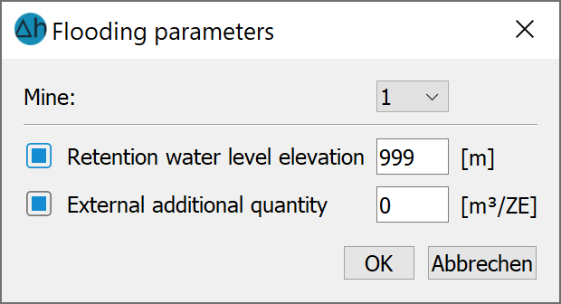
Flooding parameters…
If the GRUB attribute (balance node for mine flooding) has been assigned, the following input window can be used to assign the reservoir target and the external addition rate for the individual pits/voids. A detailed description can be found in the "How To - "Flooding simulation of mine structures".
Van-Genuchten-parameters…
If the USAT attribute is present in the model file, the parameters of the individual saturation ranges can be defined via this menu item:
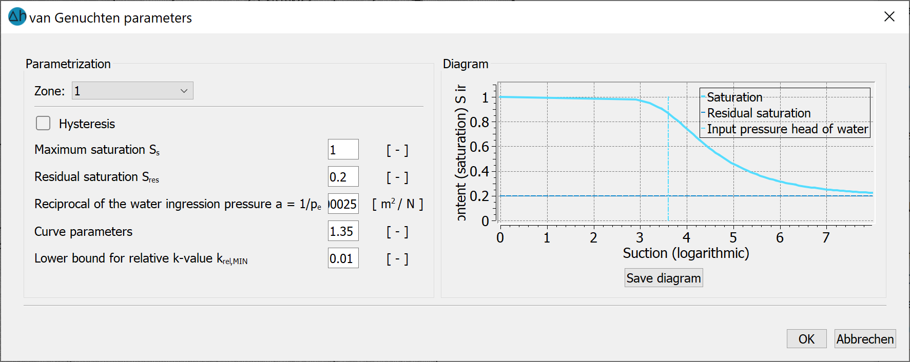
This menu item, including the input window, is described in detail in the chapter "Data structure of the groundwater model - saturation parameters, hysteresis".
Adjust factor vertical/horizontal K-value …
After selecting this menu item, the following input window appears:
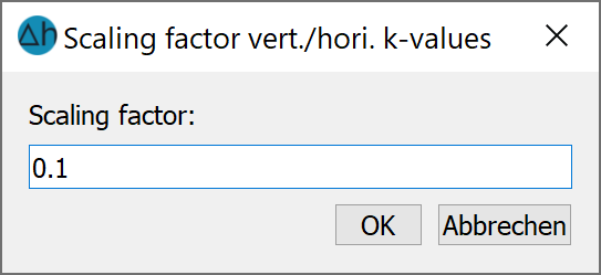
A global scaling factor can be entered here for the ratio between vertical and horizontal hydraulic conductivity for 3D models. The default value is 0.1 (1 to 10).
Anisotropic conductivities …
As this menu sub-item is very complex, it is dealt with in a separate sub-chapter.
Define new data type
After selecting this menu item, the following input window appears:
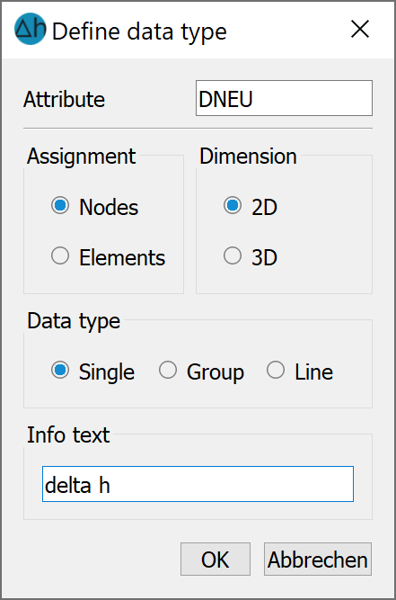
Here new data types can be defined, which are not registered in the file xsusi.kenn. Details can be found in the notes in the chapter "Information of the file xsusi.kenn".
Import data/computation results…
This menu item can be used to import model data from other directories as well as calculated data from the background files into the model file.
The following input window appears:
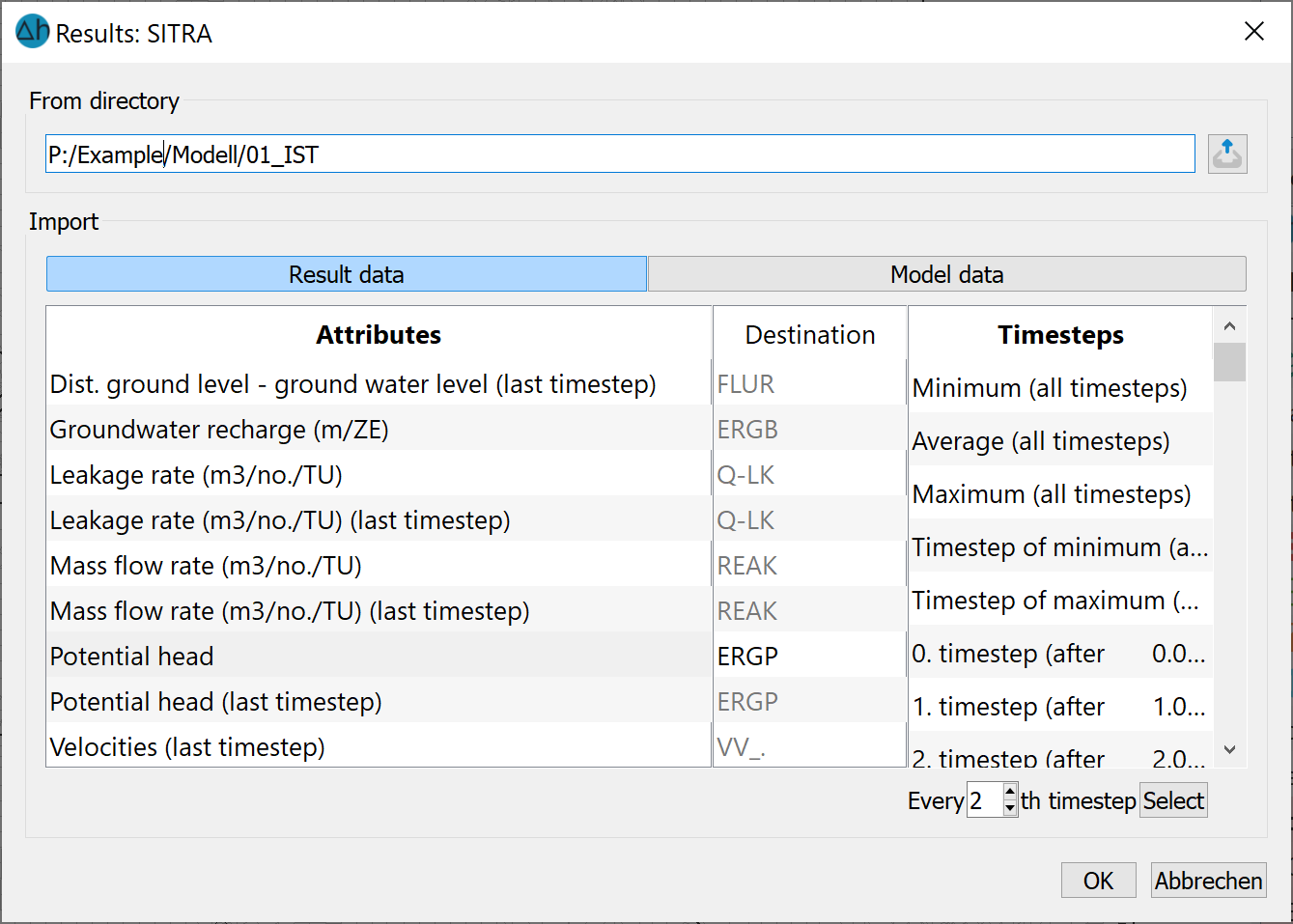
The directory must be selected in which either the calculation run whose results are to be read-in was saved or in which the desired model data is located. (No check is carried out as to whether the results saved in the background files match the current project).
If result data is found, a list appears for selecting the data to be transferred. The target attributes are specified by name, but can be changed by clicking on them.
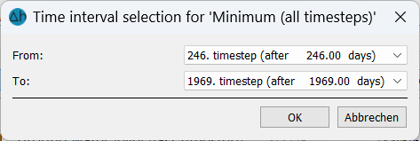
The data record is saved to the nodes or elements (depending on the result) under the Destination attribute identifier specified. A permissible identifier consists of a combination of 4 letters or numbers (underscore is also permitted). For all result data with the exception of velocities, any identifier can be entered, including an identifier unknown to SPRING. SPRING automatically recognises via the type of data type (node or element) whether the identifier must be saved as a node or element data identifier. If velocities are selected, these are automatically saved on the element data types VV_X, VV_Y and possibly VV_Z. In this case, no identifier can be entered. In addition to the data for each time step, the minimum, maximum and average values of the transient result data can also be read in. You can even use the right mouse button to specify a specific time period for analysing the minimum, maximum and average values for some types of data. The following input window then appears.
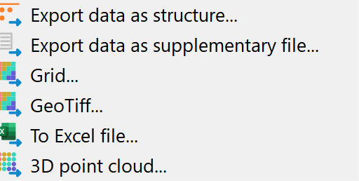
Export…
This menu item can be used to output data in structure data format, in grid format or as an Microsoft Excel (*.xlsx) table:
In structure format (I6, F10, F10, F10), the data is output as a *.txt file. The following input window appears:
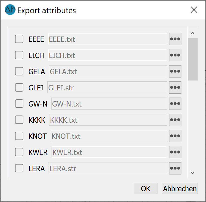
By clicking on one or more buttons the attributes to be exported are selected. Subsequently, the desired layers in a 3D model and the name of the output file are specified. With the button Browse a different directory in which the data should be stored can be selected. By clicking on the OK button the export starts.
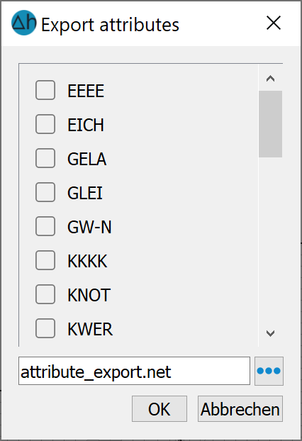
If data is to be exported in the format of an additional model file (*.net), the following input window appears:
After selecting the data type, it is saved in the format of the model file (name_additional.net).
After selecting the data type, it is saved in the format of the model file (name_additional.ne
In grid format, the data is output as a *.grd file:
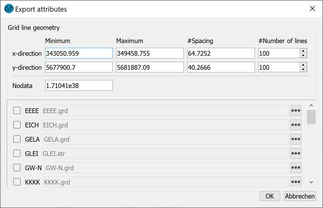
The attributes to be exported are selected by clicking on one or more buttons. The desired layers in a 3D model and the name of the output file can then be defined. The Browse button (…) can be used to select a different directory in which the data is to be saved. Click on the OK button to start the export.
When exporting in GeoTiff format, a virtually identical input window appears, which differs only in the file extension *.tiff.
When exporting as an Excel file, a list of possible attributes also appears, which are then saved in *.xls format (x, y, value
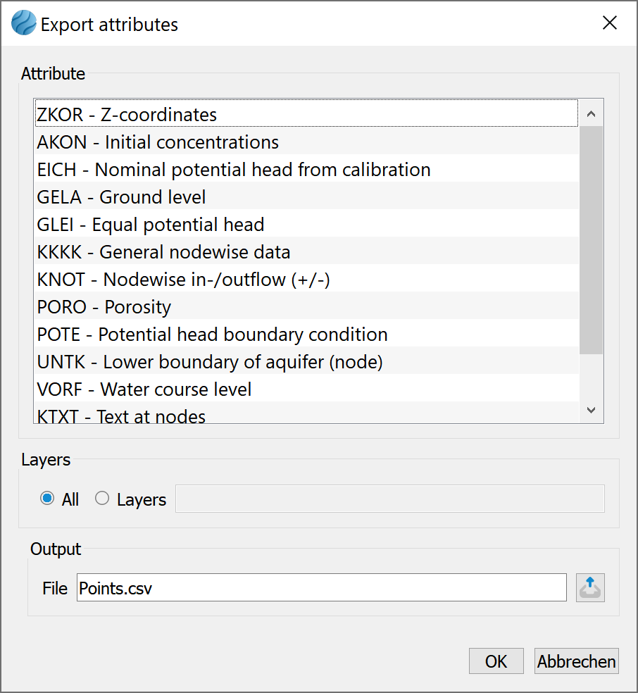
When exporting as a 3D point cloud, a list of possible attributes also appears, which will then be saved in *.csv format (x, y, elevation (z), value).
Find and replace...
This menu item can be used to automatically replace attribute values or attribute characters in one or all layers (in the 3D model) within the model file. Any existing attribute character is not automatically replaced, but must be specified.
The following input window appears:
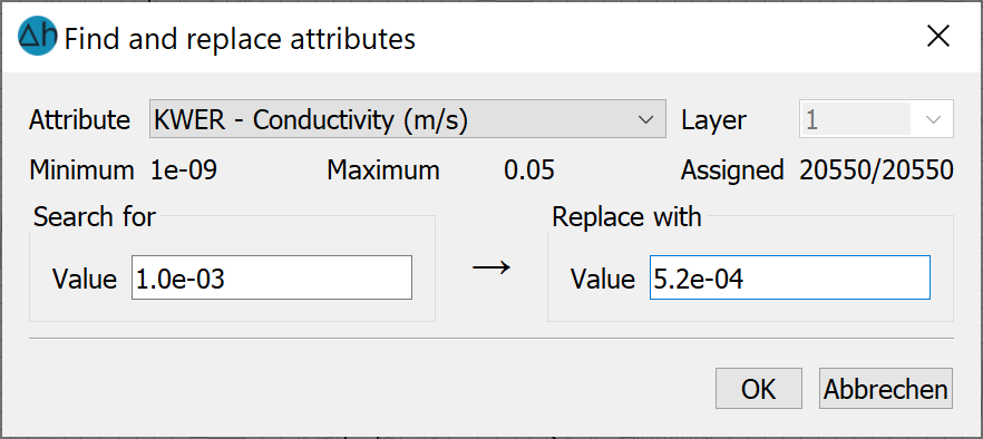
The minimum, maximum and number of occupied values are given for orientation.
The "All layers" checkbox can be used to search for and replace values in all layers simultaneously.
Delete…
This menu item can be used to delete existing data. It is possible to delete individual attributes or several attributes at the same time:
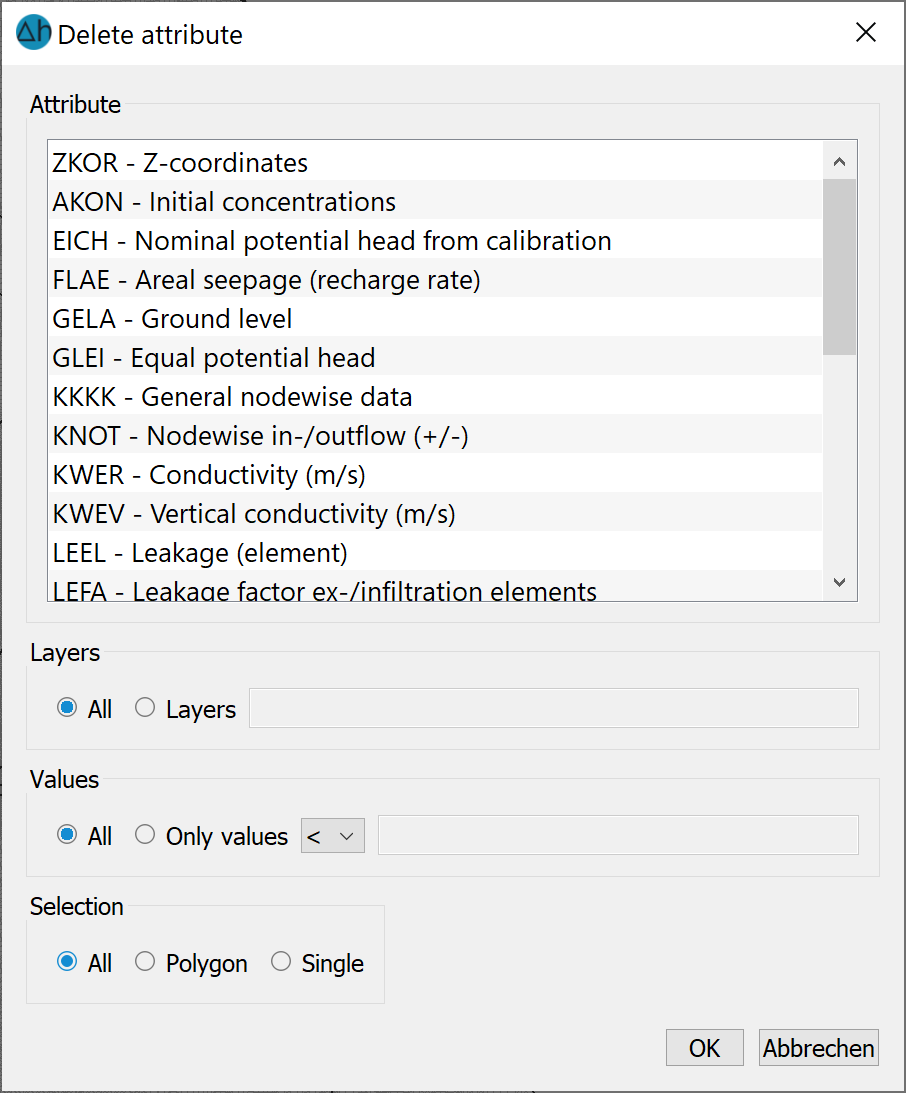
The data of all layers or only a specific layer can be deleted in a 3D model.
All values or only those with a specific value can be deleted globally, or only in a polygon which can be defined. The various options can be combined as required (e.g. "only the POTE in layer 3 in a specific area" or "only LERA in a specific area with the value 200.0" ...).
Only the values of nodes/elements that lie completely within the selected polygon are deleted.
Stand: 02.06.2025 | 