After selecting Calculation  Interpolation..., the following input window appears:
When the Interpolation window is called up, the programme reads in the batch file with the default name inter.bip (if it exists) and the default settings in the screen are changed according to the information stored in the batch file if necessary.
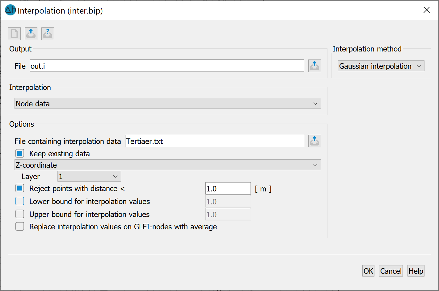
The name of the output file (default: out.i) is entered in the "Output" block.
The interpolation type is defined in the "Interpolation" block. A distinction is made between:
node data
element data (interpolation to the element centres)
groundwater contour map (only available in a 2D model)
node track for multiple time steps
The selection of the interpolation type influences the appearance and options available on the input window. If you select "Groundwater contour map", further input options open up, while the block for the interpolation algorithm closes if you select "Node track for multiple time steps".
Options
This block contains information on the data and settings to be taken into consideration for the interpolation.
Selection of the File containing interpolation data:
The interpolation data file may only contain lines with the following information: any number, x-coordinate, y-coordinate, value
(format I6, 3F10.2 = format of the structural data). There must be no blank lines between the data.
Keep existing data already present in the *.net file:
If this is to be done, a selection list of the available data types in question appears after activating the checkbox. Please note that the data is used in the specified units. In the case of model data, these are not necessarily the units in which the data was entered. This selection is only available if node or element data is to be interpolated.
Reject points with distance < (smaller) than a defined minimum between the interpolation points:
The Kriging and Gaussian interpolation algorithms, as well as the interpolation for groundwater contour maps, must not contain any duplicate coordinates.
Define a lower and upper bound (limit) for interpolation values:
After interpolation, the calculated node or element values are limited by the specified extreme values (e.g. subsidence should not be negative!).
When interpolating node data, the GLEI boundary conditions defined in the mesh file can be taken into account:
At the GLEI nodes, the interpolated values are replaced by an average value so that, for example, all nodes of a lake with groundwater interation have the same value. This menu item is omitted when interpolating element data or if the GLEI attribute is not assigned.
Additional interpolation points can be taken into account when interpolating a groundwater contour map. The procedure is described in detail in section 6.2.2.
The interpolation method to be used is selected here. The following algorithms are available:
Depending on the selected method, further input options open up, which are described in more detail in the following chapters. The Area and Gaussian interpolation methods are described using the interpolation module in the SPRING attributes menu.
The buttons at the top of the input window allow you to reset the input parameters ( ), open an existing batch file (
 ) or save the current batch file under a different name (
 ). The buttons at the bottom of the input window start the calculation (OK button), close the dialogue (Cancel) or open the digital help (Help button).
Stand: 30.01.2025 | 