The Structure menu can only be selected in Model file mode. The following menu items are available:
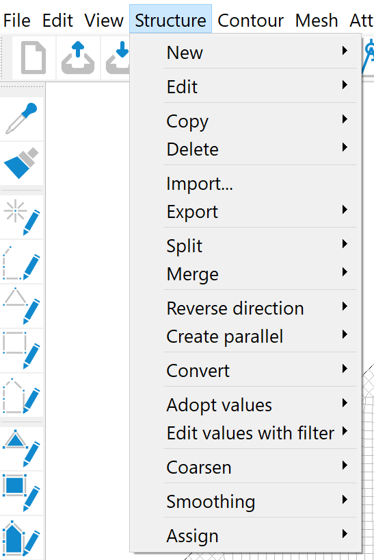
New
The following actions can be selected in the New submenu:
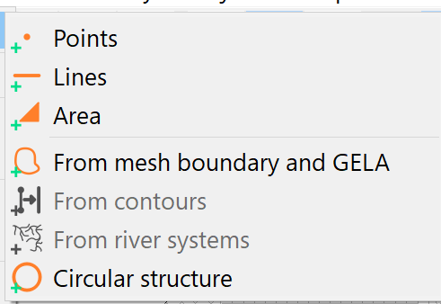
Firstly, the type of structure to be created is selected:
Points
Lines
Area
From mesh boundary
From contours
Circular structure
After selecting the structure type, the desired structure can be created in the main window of SPRING. After confirming with the right mouse button, the input window appears: "Modify (p-, l-, f-) structure".
This input window is explained in detail during the description of the menu item Structure  Edit.
Edit.
The menu item From mesh boundary creates a new l-structure (line) on the mesh boundary (with points at all boundary nodes) and assigns (by default) the values of the terrain surface to these.
The From contours menu item creates new structures from the existing contours. It is only active if contours already exist.
Circular structure
A circle structure can be created by activating the corresponding menu item. Use the selection cursor to define the centre of the circle. An input window appears in which the parameters of the circle are defined:
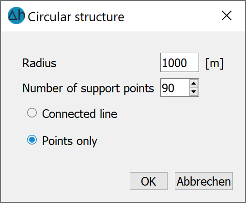
The number of points describes the number of structure points that are to be created for the discretisation of the circle. With 90 points, the point spacing is 4° of the circumference of the circle.
The Connected line and Points only selection describes how the circle structure should be displayed:
Edit
As this menu sub-item is very complex, it is dealt with in a separate sub-chapter.
Copy
The selection of which structure is to be copied is made in the submenu. Individual structures can be selected using Pick or List. However, it is also possible to copy all structures.
Please note that if there is only a single structure defined in the model and you attempt to copy a structure using the List option (or use the List option for any action with just a single structure in the model), then the software will bypass the list and perform the relevant action on the single structure. For example, the existing structure will be automatically copied without displaying the list menu.
The selected structure is copied in its entirety (attributes, structure type, coordinates, values and display attributes). A copy can be recognised by an @ appended to the structure name. For example, a structure with the name Struct would be copied as an item named Struct (@1). Additional copies will have an increase in the integer that follows the @, e.g. @2, @3.
By copying structures, you can, for example:
Several geometrically identical structures with different identifiers and values can be generated. For example, a line structure for a receiving watercourse may be copied three times: one copy for the receiving water elevation (attribute VORF), another for the leakage coefficient (attribute LERA) and one for the automatic marking of the polygon course (attribute MARK).
Geometrically similar structures can be created by copying and subsequently editing the copied structure.
Structures that are to be converted into transient structures. This process cannot be reversed and is thus safer to perform on a copy of the structure.
Caution: As the original and copy of a structure lie on top of each other, only the copy is found when snapping, as this is displayed as the first object. Selecting the structure from the list helps here.
Delete
The following items are available in the Delete submenu:
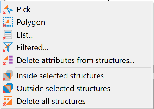
When picking (separately), one or more structures are selected and deleted one after the other. When (picking) polygon, all structures in the selected polygon are deleted.
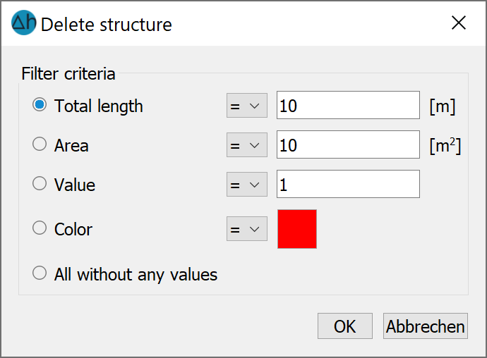
If List... is selected, the structures to be deleted can be selected within the list. If only a single structure is present then that structure is automatically deleted when selecting the List… option. If you select Filtered... another selection window appears for defining the filters:
When selecting Delete attributes from structures..., a selection window appears for defining the attributes to delete:
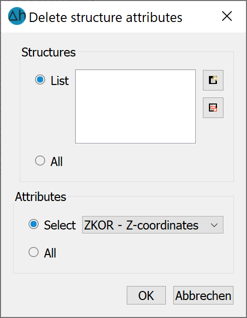
The attribute selection can be used to delete specific attributes from structures for which several attributes have been assigned, or all attributes of a type can be deleted.
If All inside/outside selected structures is selected, the corresponding structures inside or outside the selected area are deleted.
If you select Delete all structures, all structures are deleted.
Import…
As this menu sub-item is very complex, it is dealt with in a separate sub-chapter: Importing from other formats.
Export…
The Export... menu item offers the option of either exporting a selection of structures via the List... item or exporting all structures using the All... item.
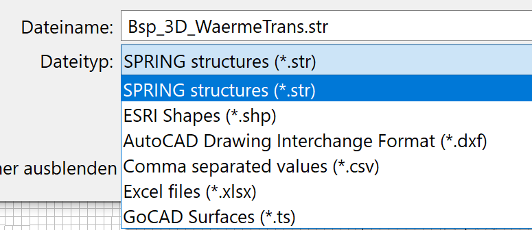
The export data type and storage location are first defined in the file selection window. The following export options are offered for structures:
If only a selection of structures are to be exported, the list dialogue can be utilized to select the desired structures for export).
Split
Existing line structures can be split at several points using this menu (e.g. to split a LERA structure for the assignment of different leakage coefficients in sections).
If a line structure is selected (pick/list), it is automatically separated at the selected division points. Identifiers, structure type, coordinates, values and display attributes remain identical to the original structure. Only the info text of the structures is supplemented by the text "(n)", where n is the number of the corresponding section.
Merge
This menu can be used to combine two point or line structures into one structure.
It is possible to pick the point or line structures either interactively on the screen or via the list... menu item to select them.
If two point structures are selected, the points (x, y + values) of the second point structure are added to the first point structure. Keep in mind that the info text of the second point structure is lost with this action!
If two line structures are selected, the distances between the structure start and end points are calculated and the two structure lines are combined at the ends where the calculated distance is the smallest. If the selected line structures have a common start or end point, this can lead to the value information of one of the two points being lost in the combined line structure. The new line structure inherits the info text of the first selected line structure. The info text of the second line structure is lost during this action!
Reverse direction
This menu can be used to change the direction of a line structure. This can be important for river system structures.
Create parallel
The procedure and the input windows for this menu item are explained in detail in the chapter "Adding a new structure to an existing model".
Convert
Firstly, a submenu appears in which the following selection options are available:
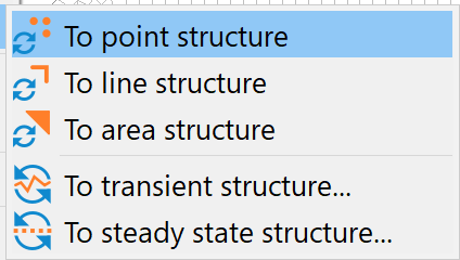
After converting the selected structure, the conversion can be confirmed by the structure type (p, l, f) column when viewing the structure list. Conversion is possible towards any type and in any direction.
When converting to a transient structure, the change in the structure list can be recognised by the "g" in front of the structure type.
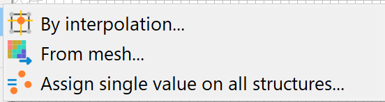
Adopt values
The following menu item appears:
This menu item is only active if at least one point and one line structure are available.
By interpolation
The following input window appears:
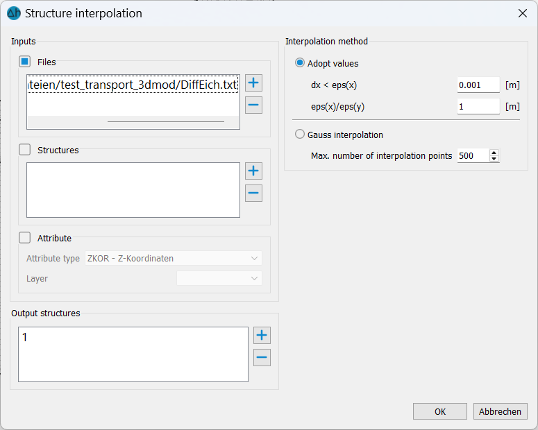
The data sources for the interpolation values for the target structure can be files (formats: *.str, *.txt, *.asc, *.dem, *.grd, *.tif), other structures or model attributes.
From mesh...
After selecting the desired structure, an attribute of the model file can be selected from a list whose values are to be assigned to the structure.
Assign single value on all structures
This menu item can be used to assign a standardised value to all structures. The following input window appears:
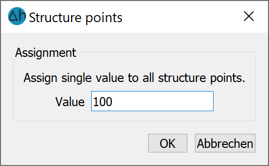
After entering and confirming the value with OK, all line, point or area structures receive the entered value at their existing structure points.
Edit values with filter
After selecting one, several or all structures and confirming with the right mouse button, the following input window appears
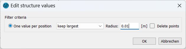
With the help of this menu item, superimposed structure values, which originate from three-dimensional point clouds, for example, can be deleted. The largest or smallest value can be selected.
Coarsen
After selecting the appropriate structures, a submenu appears,
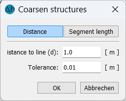
in which the maximum distance for the coarsened line structure is defined. Points are deleted if the distance of the point to the simplified line is smaller than the defined distance.
Smoothing
After selecting the structures for smoothing the following input menu then appears:
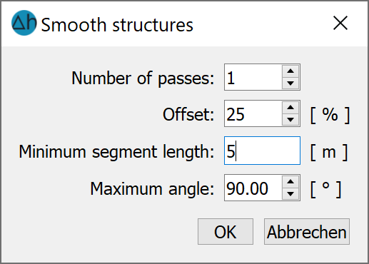
Number of passes: The number of passes here is the same as the number of smoothing iterations.
The division offset of the segment (between 0-50%) means: 25% creates new points along the line of a segment at 25% and 75% for each pass (smaller values = "tighter" smoothing).
Minimum segment length: Defines the minimum length of a segment after smoothing takes place, starting from >= 2 m.
Maximum angle (0 - 180): This defines the angle between neighbouring segments up to which smoothing is to take place.
Example (red: original structure, blue/green: after smoothing):
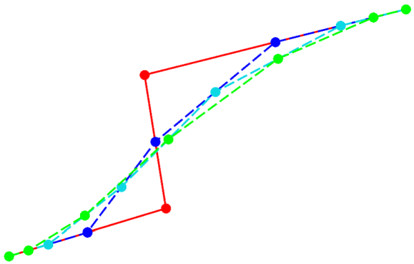 Smoothing 1st 2nd 3rd
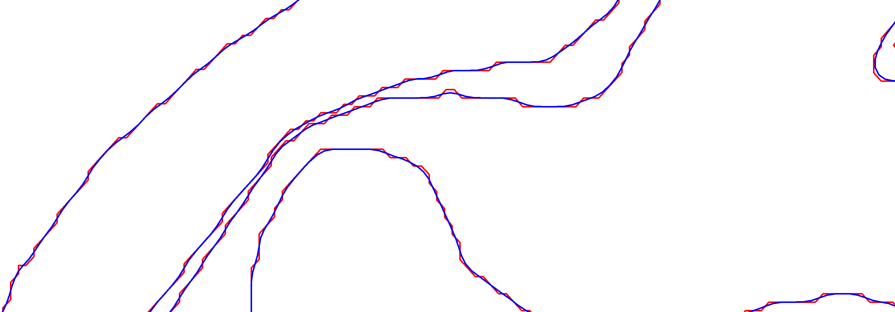
The following figure shows the initial structure (red) and the result of the smoothing (blue).
Assign
As this menu sub-item is very complex, it is dealt with in a separate sub-chapter .
Stand: 10.04.2026 | 