This chapter presents the user with a concept for retrofitting a new structure into an existing mesh.
Before starting any subsequent editing of the mesh geometry, it is advisable to create copies of the original mesh and structure file. All attribute data that is affected by deleting an element area should be saved via: Attributes  Export.... A list of all existing attribute data appears. By selecting the individual attributes, these can be saved as independent files in the structure file format so that they can be reassigned (interpolated) to the changed mesh at a later date. Do not forget the data of the 3D file in the 3D model!
Alternatively, save a copy of this model in a new folder with the File  Save as… menu item or the Save project as… toolbar button. The changes we are going to make are not required for the model we are building, and thus will be discarded at the end of this exercise. As a result, please have a copy of your model available from before the new structure is included. It is always advisable to save models in different folders, some of the files generated by the model can cause confusion between multiple model files.
After the aforementioned preliminary work, the step-by-step inclusion of the new data now begins.
Delete elements in the area of the new structure over a wide are
First of all, the nodes or elements in the area of the new structure are deleted via the Mesh → Nodes and Elements  Delete
  Polygon menu items.
Create the new structure:
Structure  New
New  Lines (sheet pile wall)
For this example, let’s add a sheet pile wall to an arbitrary location. To discreticise a sheet pile wall, it is possible to automatically generate an identical second structure parallel to the first structure. The distance between the two structures can be freely selected. To do this, first select the structure under the menu item: Structure  Create parallel
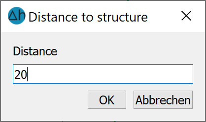
  Pick/List, once the structure is selected use the left mouse button to determine the side on which the parallel is to be created (click inside or outside for surface structures). An input window then appears in which you can enter the desired distance:

Distance of the parallel to the structure (m)
To make the parallel structure visible, a distance of 20 metres was entered here. After confirming with the right mouse button, the structure appears in the grid.
Adopting the new structure as a contour
Contour  New
New  From structure
  Pick
Pick
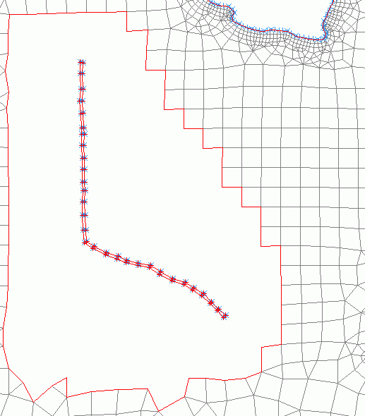
The following image shows a model section of the new structure with its parallels:

Model with new structure and already assigned contour (blue)
Create new mesh nodes:
Mesh  Mesh generation
  Generate Mesh
  Region…: Snap to Mesh node. Here it is important to snap all nodes of the existing boundary! The node spacing dx should correspond approximately to the existing side length of the elements (in the example dx = 120.0 m). Some nodes are inserted manually for a clean element meshing.
Note: If there is a closed contour border, nodes can only be generated within this contour border.
Example: An area in an existing model is deleted, e.g. to add a new structure. A closed contour is created for this structure. At this moment, it is only possible to create nodes within the structure contour. Only when this contour is deleted can nodes be created again outside the structure.
Create new elements:
Mesh  Mesh generation
  Create Elements
  Triangles and quadrilaterals (from inner boundary): The area in which new elements are to be generated can be selected immediately with a single mouse click.

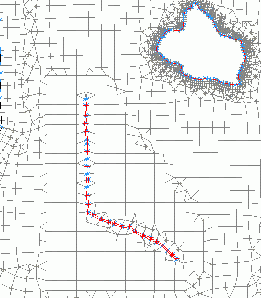
New nodes and elements in the area of the new structure
After completing the mesh, geometry checks must be carried out and the data saved!
As there are fractures in the database in the area of the newly generated elements, the missing data must be supplemented by reassigning the attributes (Attributes  Assign
  By interpolation...).
For large amounts of data, it is necessary to reduce the stored attribute data to the affected area before the new assignment. This is done via the Structure  Import… menu item. For example, import a *.txt file, assign the columns and attribute identifier, then Structure
  Edit
Edit  Pick or List… and using Points: Delete in polygon. By selecting the "Invert selection" button in pick mode, it is sufficient to select the area to be assigned, the rest will be deleted.
When asked for the interpolation algorithm, "Gauss" should be selected, as well as "Keep existing data" and "Filter data with less distance".
Remark:
If the value of only a few nodes has changed due to a local mesh change, the following is recommended:
If the existing node data of the unmodified nodes is sufficient for interpolation, interpolation without importing an ASCII file and without additional data from structures is generally only sufficient with "Keep existing data". The Gaussian algorithm is suitable for node data, even with a large number of nodes, as all existing node data that is not in the neighbourhood of the nodes to be interpolated is deleted from the interpolation points before interpolation.
If element data (e.g. groundwater recharge rates or hydraulic conductivity) that are constant in some areas need to be updated due to local mesh changes, the following procedure is recommended:
The values can be interpolated without importing additional ASCII files and without additional data from structures only with "Keep existing data". By means of Distance weighing, setting a very large search radius and setting the number of minimum and maximum interpolation points = 1 (exactly one interpolation point), it is possible to ensure that the corresponding elements receive the value of the element closest to them which has data.
Step 3: Data assignment  illustrates the different options of data assignment to the finished FE mesh.
