This section begins with a brief description of all menu items and editing steps. The node generation algorithms are then described in detail. The following menu items are available:
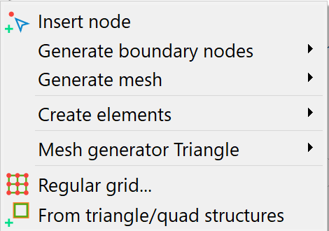
Insert nodes
The left mouse button can be used to create mesh nodes at any point.
Generate boundary nodes
The algorithm is described in the chapter: "Boundary nodes generator algorithm".
The generation of nodes at the contour points and normal to the contour sections is the first step in node generation. It requires that a closed contour boundary exists! Therefore, when the Generate boundary nodes – Global… or Region… menu items are activated, the contour boundary is calculated first. If the calculation of this contour boundary is successful, the following submenu appears to define the number of passes (n):

The number n defines the number of passes or the distance up to which edge nodes are to be generated normally to the contours.
For a project without fracture contours (k-contours), only the query for the number of passes appears. If the number 0 is entered here, only the nodes on the contour boundary points are created.
The length factor for k-contours is generally used to reduce the generation distance for fracture contours and the number of Additional points can be used to control the discretisation density normal to the fracture. The boundary node algorithm generates the nodes with exponentially increasing distance to the fracture.
Region…:
If the calculation of the contour boundary is successful, the area in which the boundary nodes are to be generated must be defined. It is important to ensure that all existing mesh nodes are included when defining the boundary polygon for node generation.
Notes:
It is recommended to call up the boundary node generator with at least the 0th initialisation step, as problems occur during mesh generation if there are no mesh nodes at contour nodes. In addition, 1 to 2 boundary node generation steps are recommended, depending on the model type.
If a larger number of generation steps are to be carried out in certain areas, the following procedure is recommended:
First, the boundary node generator is executed with the smaller, globally sensible number of generation steps. In a second step, all nodes in the area in which more generation steps are to be carried out are deleted. The edge node generator is then executed again with the larger number of generation steps. In this case, no new mesh nodes are generated from contour points that lie outside the deleted area, as the 0th step of the boundary node generator already fails due to the cancellation criterion "nearby mesh nodes already exist" and therefore no further generation steps are carried out from these points.
Generate grid
The algorithm is described in section „Algorithm of the node grid generator“.
The generation of a node grid (Global.../Region…) requires that a closed contour boundary exists, which is why the contour boundary is also calculated here first. If the grid is to be generated in an area, the area must first be defined. When defining the polygon for the node generation boundary, make sure that all existing nodes are included:
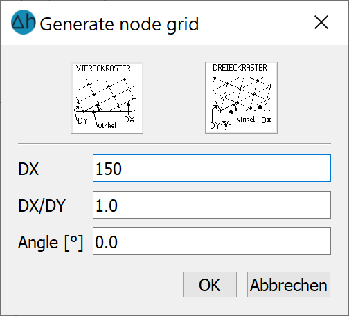
The nodes are generated in such a way that they are meshed to form equilateral triangles or quadrilaterals as much as possible.
The default setting for the grid type is a quadrilateral grid; a triangular grid requires more memory and computing power due to the higher number of elements. It is thus suggested to keep most of the mesh as quadrilaterals, and rather designate high complexity or interest areas for triangular meshing.
The default setting for the size DX for the global node grid generator is calculated from the average length of the contour sections of the outer contour boundary (without taking division points into account) scaled by 0.3.
The default setting for the DX/DY ratio results from the ratio of the scales set for the project in the x and y directions: In 2D horizontal models and 3D models, the scales for the x and y directions are usually identical. The preset ratio DX/DY=1 then leads to the generally desired regular grids. In vertical models, the y-direction is often exaggerated in relation to the x-direction. The preset value DX/DY>1 from these scale settings then results in the desired rectangular grids with a large edge length horizontally and a small edge length vertically.
The element edges can be rotated relative to the horizontal by entering an angle.
The origin of the node grid is set to the minimum x- and y-coordinates of the contour boundary during generation.
The use of this menu is explained in more detail in chapter "Step 2, Create node".
Generate elements
The elements of an FE mesh can be created in different ways with SPRING. Models can be created with triangular elements only or models with triangular and quadrilateral elements.
The Create elements menu item therefore has the following submenu:
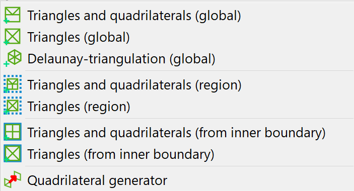
Generating Triangle, Triangles and quadrilaterals (global/region/from inner boundary):
After checking the closed contour edge and possibly defining the region/inner boundary, triangulation is started.
All existing elements that lie completely within the defined area are deleted (including data!).
The nodes within the area are meshed with triangles, taking into account all contours that lie completely within the polygon.
When selecting the generation of triangles and quadrilaterals, suitable triangles in the region are combined into quadrilaterals after meshing with triangles.
The menu item Triangles and quadrilaterals or Triangles (region) can also be used to create elements manually.
When defining the polygon for a region-based triangulation, ensure that the individual sections of the boundary polygon are used by the mesh generator as subsequent element edges (record all nodes in the polygon definition).
The greater the number of nodes and the more contour sections to be considered by the meshing algorithm, the longer the triangulation of the elements can take.
Delaunay triangulation (global
This menu item can be used to perform a Delaunay triangulation. Only triangles are generated with this algorithm. Suitable triangles can then be combined into quadrilaterals using the Quadrilateral generator menu item
Quadrilateral generator:
This menu item can be used to subsequently combine suitable triangles into quadrilaterals in a triangle mesh. Please note, however, that the data of one of the two triangles will be lost when combining two triangles into a quadrilateral!
Mesh generator Triangle…
The use of the Triangle mesh generator is described in detail in the chapter "Setting up a 2D model: Using the external Triangle mesh generator"
Regular grid…
The generation of a regular mesh is described in detail in chapter "Building a 2D model: Creating a FE mesh using automatic mesh generation"
 Algorithm of the boundary node generator
Stand: 06.05.2025 | 