The mesh menu can only be selected in model file mode. The following menu items are available:
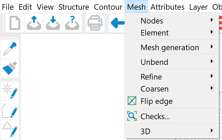
Nodes
In the Node submenu the nodes can be edited accordingly. The following options are available
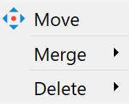
Move
This menu item can be used to change the geometric position of existing mesh nodes using the mouse cursor. It is possible to move the selected node to any coordinate (Free) or to an existing point (Snap mode) by holding down the left mouse button.
When moving mesh nodes, care must be taken to ensure that no unauthorised elements are created, e.g. that nodes are moved into other elements.
You can undo the move with the Edit → Undo menu item or selecting the  symbol. When moving nodes, the attributes assigned to that node remain unchanged! Depending on the attribute, a new assignment of attributes may be necessary when moving the node. For example, moving a node by several metres may require a new interpolation of the terrain height or a receiving water potential at this node.
Merge
It is often only after meshing the generated nodes that it becomes apparent that two nodes that are very close to each other can be merged. It can also happen that two models with a common boundary are to be merged into one model. In these cases, this menu item automatically executes the following steps:
Move the node coordinates to a geometric centre point,
Averaging of node data that is available for both nodes (with the exception of node withdrawals/inflow rates).
Delete one of the nodes, and
Correction of the incidences of the elements adjacent to the nodes.
The nodes that are to be merged can be selected in various ways:
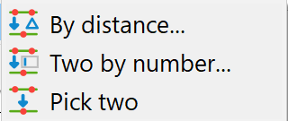
By distance...: An input window appears in which a maximum distance is entered in the xy and z directions:
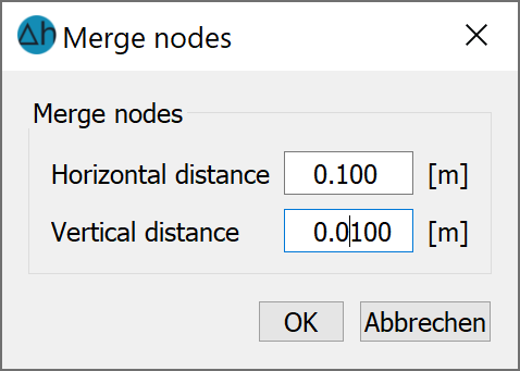
With an exaggerated vertical model, it can be useful to specify a greater accuracy in the horizontal xy-direction than in the vertical z-direction. All nodes whose distances to each other are smaller are automatically merged by SPRING and highlighted in colour in the main window.
Pick two: Two nodes are selected directly with the left mouse button.
Two by number...: An input window appears in which the two node numbers can be entered:
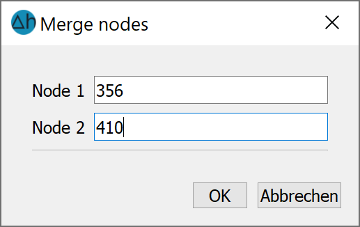
In case of a super elevated vertical model, the distance in the x-direction should be larger than the one in the y-direction. All nodes whose distances are smaller than the entered values are merged automatically by SPRING, they are coloured and displayed in the main window.
Delete nodes:
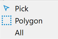
The following submenu appears:
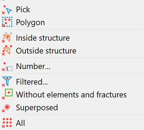
The nodes can be deleted individually (Pick), within an area (Polygon), within or outside of selected structures, or by specifying a number.
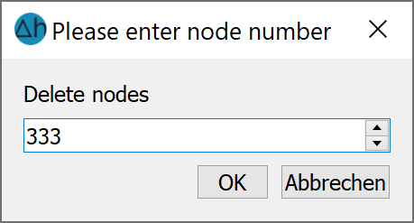
In the Number... menu item, an input window appears in which the noder number of the nodes to be deleted is entered:
It is also possible to delete nodes that do not belong to any element or fracture, or whose coordinates correspond to another node (delete consecutive nodes).
Note: If a node is deleted, all neighbouring elements are also automatically deleted.
The menu item "Delete node 1 and close mesh with node 2 - snap" allows the user to delete a node (node 1, select with the left mouse button) by moving node 1 to another node (node 2) and merging it with this node. No elements are deleted during this process. Node 2 can be selected with the left mouse button, or the next node is automatically selected by the programme by pressing the right mouse button. The element and node attributes are retained.
Element
The menu item Mesh  Element Delete offers various options for deleting one or more elements:
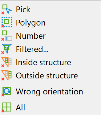
The elements can be deleted individually, in a range or by number.
In the submenu item Delete Number..., an input window appears in which the number of the element to be deleted is entered.
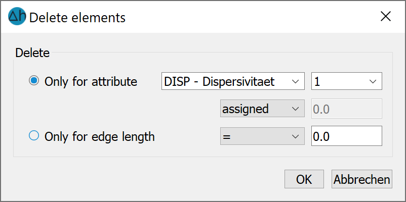
In the submenu item Delete With filter... an input window appears in which an element can be deleted based on its attribute value:
When deleting elements using selected structures, only those elements whose nodes and element centres are completely inside or outside the structure or on its edge are deleted.
The following should be noted regarding the submenu item Delete Wrong orientation:
In SPRING, elements are always generated in an anti-clockwise direction. If the user has created elements with the wrong orientation by manually editing the model file, they can be automatically deleted here.
The All menu item deletes all elements!
Mesh generation
As this menu sub-item is very complex, it is dealt with in a separate sub-chapter.
Refine
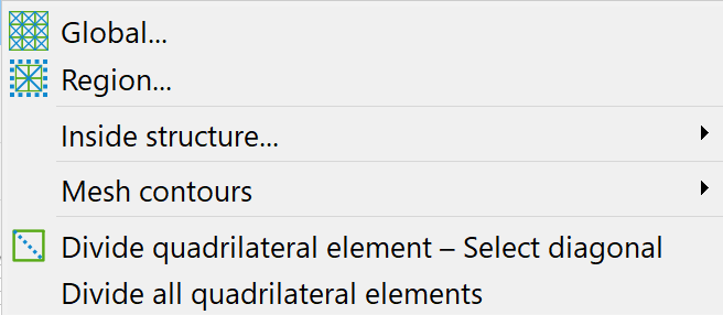
The following submenu appears:
When the Global... menu item is selected, a query appears asking how many refinement steps should be carried out:
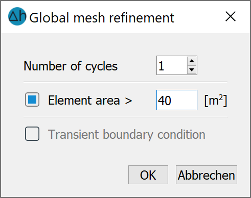
Each pass divides each element into 4 new elements and halves each side. One refinement step therefore halves the element size in the refinement area, the second pass quarters the element size and so on.
If a transient input file was imported prior to mesh processing, the transient data is also refined.
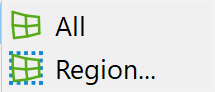
If Region… or Inside structures… are selected, only the elements in the corresponding areas are refined. The procedure largely corresponds to that of global refinement. When refining an area, a minimum element size can also be specified. In the area between the refined and unrefined elements, new nodes must then also be generated and elements split in order to create a transition. This means that elements outside the selected area are also refined. There are two different strategies for handling this transition:
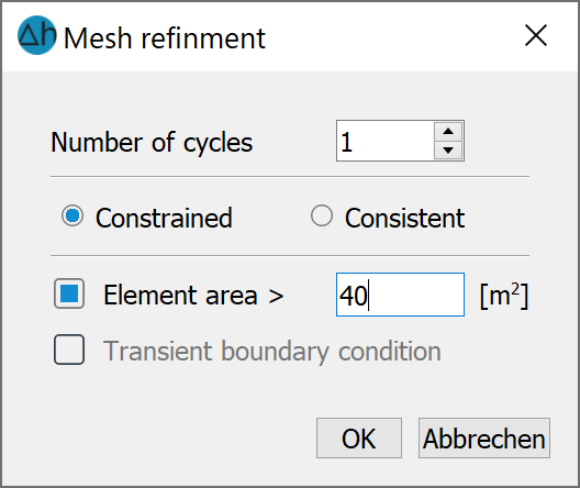
Constrained refinement:
At the edge of the refinement area, elements can be created whose aspect ratio is not equalised. With limited refinement, poorer aspect ratios are accepted than with consistent refinement. This makes the transition area to the non-refined mesh thinner.
Consistent refinement:
If the bisection of an edge leads to undesired aspect ratios in the neighbouring element, the edges adjoining this edge are also automatically split in this element. This can result in very short edge lengths. It can also lead to the transition area between the refined and non-refined elements becoming relatively wider.
If a transient input file was imported prior to mesh processing, the transient data is also refined.
For Inside structures…, a structure must be selected with a left mouse click after confirming the input window with OK. To do this, the structure must first be displayed.
Mesh contours:
If new geometries (e.g. building outlines or new drainage trenches) are to be added to an existing mesh at a later date, these can be added automatically using this menu item. Only the corresponding contour must be created beforehand. After selecting one of the following selection options
the contours to be included can be selected.
Divide quadrangle element - select diagonal
The "Divide quadrilateral element" menu item allows you to automatically divide a quadrilateral element into two triangles along one of its diagonals. The corner nodes whose diagonal is to form the new element edge are selected with the left mouse button. The attributes of the split element are retained in the new elements.
Divide all quadrilateral elements does the same as the above automatically and globally.
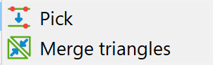
Coarsen
Coarsening of the mesh can be done by selecting two nodes (pick individually) or two triangular elements (combine triangles:
Flip edge
This menu item can be used to change the diagonal between two triangular elements. The respective neighbouring elements are selected for this purpose. For example
Triangle BEFORE clipping:
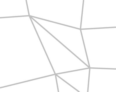
Triangle AFTER clipping:

Unbend
The mesh can be unbended/relaxed globally or in specific areas:
After meshing the generated nodes, there are usually noticeable transition areas between nodes from different generation algorithms, grids with different parameters, and manually generated areas. This menu item can be used to smooth these transition areas by automatically shifting node coordinates globally or by area (select the desired area with the left mouse button). To do this, a number of passes must be defined for the mesh smoothing:
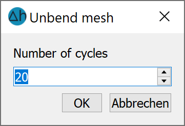
The greater the number of passes selected, the further the influence of the displacement extends into areas in which node grids were generated. In addition, a relaxation of the grid leads to the displacement of nodes that were generated logarithmically based on the well parameters in the vicinity of extraction wells.
Nodes and element edges that lie on or along contours are not moved.
Checks…
Once the mesh has been created, the mesh geometry should be checked before assigning the data. Errors in the mesh geometry can otherwise mean that no finite element calculation will be carried out.
The following geometry check options are available:
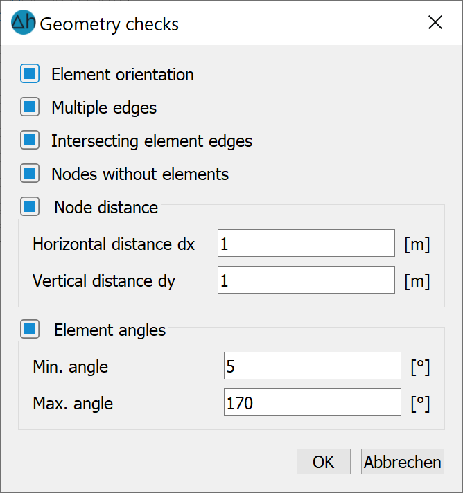
When checking the Element orientation, the system checks whether the node lists of the elements are orientated anti-clockwise. If this is not the case, this error can only be rectified by deleting and recreating the corresponding elements.
When checking for Multiple edges, the element edges are checked. Element edges at the edge of the mesh are present once, element edges inside the model are present twice and in different directions. Errors can occur due to overlapping elements or incorrect element orientations.
When checking the Intersecting element edges, all element edges are checked to see whether they intersect with other element edges. (This check can take some time for large meshes).
When checking for Nodes without elements, nodes are searched for which are not connected to adjacent elements.
The four control mechanisms mentioned are executed automatically and cannot be selected.
Checking the Node distance helps to recognise duplicate nodes or nodes that are too close together. Nodes whose horizontal x-coordinate distances are smaller than the size dx and whose y-coordinate distances are smaller than the size dy are regarded as errors.
Checking the Element angles helps to recognise elements of poor quality (with very small or large angles). A corresponding error message is displayed first:
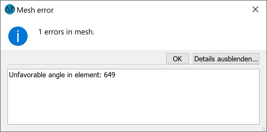
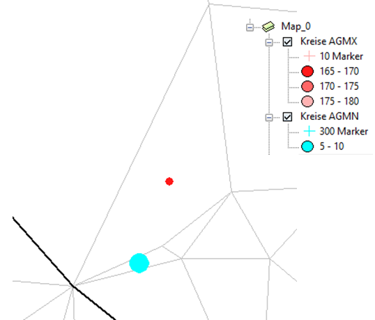
The minimum angles (attribute AGMN) and maximum (attribute AGMX) angles are stored as attributes AGMN and AGMX and can be displayed after the mesh check:
3D
As this menu sub-item is very complex, it is dealt with in a separate sub-chapter.
Stand: 06.05.2025 | 