The 3D menu is used to define settings for a 3D model. The following menu items are available:
3D-Boundary
A 3D boundary must be defined for 3D models. Various options are available for this. The following selection therefore appears in the submenu:

Mesh boundary = 3D-Boundary
When this menu item is selected, the mesh boundary automatically becomes a 3D boundary so that a complete 3D model can be created.
Generate
By selecting this menu item, a 3D boundary can be created within an existing model. This will delete an existing 3D boundary! Make sure that the 3D boundary is defined anti-clockwise and along element edges! This can be used to create a copied 2D/3D model.
Add
By selecting this menu item, an additional 3D boundary can be created within a model alongside an existing one. Make sure that the 3D boundary is defined anti-clockwise and along element edges! This can be used to create a linked 2D/3D model with several 3D areas.
Check nodes and elements
SPRING does not check the 3D boundary (attribute 3DRA) when reading in the model and therefore does not check whether the model is a complete 3D model or just a 2D model with a 3D sub-area. It is therefore always possible (but not always useful) to define attributes for the deeper layers for nodes and elements in the 2D area of a 2D/3D model! When the Check nodes and elements menu item is activated, the current mesh geometry and the current 3D boundary are used to check all nodes and elements to see whether they are within or on the 3D boundary or on the 3D sub-area.
If some elements or nodes lie outside the 3D border. For elements, the system also checks whether they lie completely within or on the 3D boundary, the status bar indicates that the 3D model is complete!
If some of the nodes and elements are outside, the status bar shows: 2D/3D model.
If elements intersect the 3D boundary, an error is signalled in the status bar. In this case, we recommend displaying the 3D edge graphically (View  3D mesh boundary) and checking it with the element geometry.
Threshold for collapsing layers…
The following input window appears
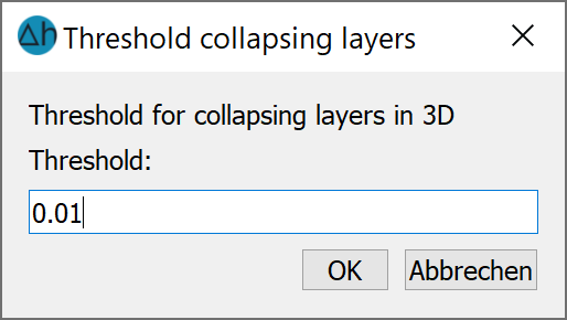
While this parameter was previously queried in the model check dialogue, it is now queried at this point and then stored as the ZEPS attribute in the *.3d file. It can also be modified within the file.
New layer arrangement
This menu item and the associated input window are explained in detail in the chapter: "Building a 3D model - Building a complete 3D model" .
Divide layer ...
This menu item and the associated input window are explained in detail in the chapter: "Creating a 3D model - adding discontinuous layers".
Delete layer ...
The layer number to be deleted is entered in the following dialogue:
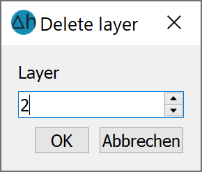
All data of layer 2 and the associated Z coordinates ZKOR 2 are deleted.
Stand: 06.05.2025 | 