During node generation, nodes are first generated on and in the area of the contours with Mesh  Mesh generation Generate boundary nodes Global.... The number of passes determines how many rows of nodes are to be generated parallel to the contours. We recommend 2-3 passes. For this example, 3 passes are selected.
The contour-free areas are then assigned grid nodes via Mesh Mesh generation Generate mesh Global....The approximate node spacing is defined in the following input window:
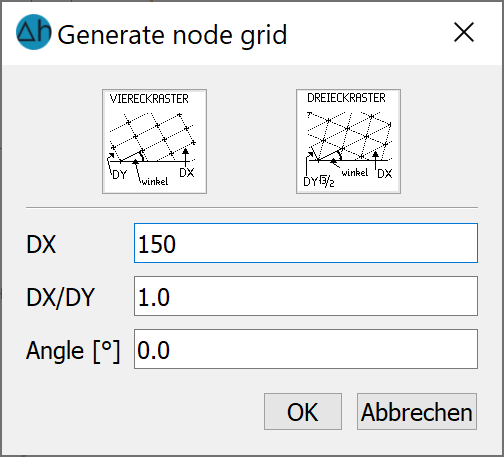
Grid node generator
In the DX field, the average node spacing of already created nodes appears as a default value; this can be modified by the user. For this example, DX = 150.0 m is set. The generated node grid then appears.
The system now checks whether the position of the individual nodes results in a homogeneous image. Nodes can be added at missing points (Mesh Mesh generation Insert node), too many nodes can be deleted (Mesh Nodes Delete) or nodes from a defined distance are merged via Mesh Nodes Merge By distance....
At this point, you can experiment with the functions mentioned and test them.
Note: To zoom, end the current function (e.g. "Insert node") with the right mouse button. Use the left mouse button to expand the desired zoom area. The current function can then be called up again using the F12 key. (This new feature applies to all editing functions!).
The next step is Creating elements
Stand: 06.05.2025 | 