To create a groundwater model, the finite element mesh must first be created. To do this, double-click on the aforementioned SPRING icon to start the SPRING graphical user interface. A startup window with several options appear. To create a new model press the Create new project button, alternatively a new project can be started in the SPRING graphical user interface by clicking on the File  New… menu item. The following window for creating a new project appears:
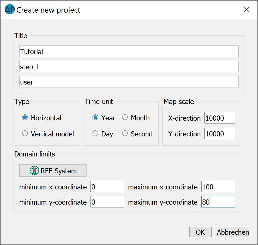
Basic data (type of model, time unit, map scale, coordinate reference system, domain limits in the x- and y-directions) can be specified here. In the example, the scale is set to 1:10,000 and the Y-coordinate to Y = 80 metres. After closing the window with OK, you return to the SPRING graphical user interface. The basic information for creating the finite element mesh (FE mesh) has now been entered. The dimensions for the FE mesh to be created are now repeated in a further dialogue via the Mesh Mesh generation Regular grid… menu item.
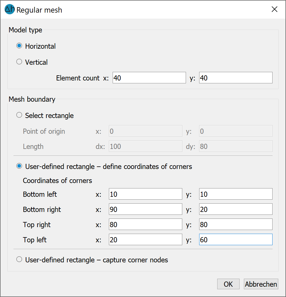
Generation of a regular mesh
In this dialogue, the number of elements in the x- and y-directions and the model type (horizontal or vertical) must first be defined.
Furthermore, the mesh boundary can be defined in three different ways:
Select rectangle:
The coordinate origin and the lengths in the x- and y-directions must be specified here. Ensure that the selected origin and dimensions lie within the area boundaries selected when creating the model.
User defined quadrangle – define corner coordinates:
With this method, the four corner point coordinates must be defined. Ensure that the selected origin and dimensions lie within the area boundaries selected when creating the model.
User defined quadrangle – capture corner nodes:
Here, the corner coordinates of the FEM mesh can be selected interactively in the user interface by selecting them with the left mouse button. The corner coordinates must be set anti-clockwise. This function is not yet implemented.
If you accept these settings by pressing the OK button and then clicking the right mouse button, the generated FEM mesh is displayed:
Automatically generated FE-mesh
It is recommended to save the intermediate status from time to time during the modelling process: The first time, the project is given its own name with the File Save as... menu item or toolbar button. In the further course of the project, it is sufficient to save the project with the File Save… menu item or button. Now the data assignment would take place, but as the automatic mesh generation is not sufficient for most problems, step 2 follows: Creation of an FE mesh with irregular constrained geometries .
Stand: 06.05.2025 | 