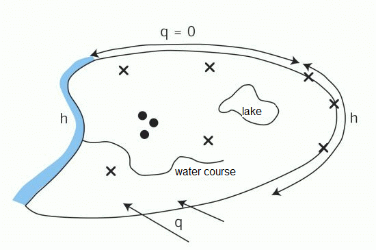
This group includes all inflows and outflows, seepage, potential heads, concentrations, well withdrawals, and the like (see figure).

Possible boundary conditions
Minimum required boundary conditions in a flow model:
For an unambiguous definition of a model, either a fixed potential head or a rate must be specified for at least one node. That node can have a value for the fixed potential head (data type POTE) or a lekage boundary condition (VORF and LERA or LEKN or LEEL defined in a at least one adjacent element).
The following options are available for the nodes of the model boundary in a groundwater flow model:
1st type or Dirichlet boundary condition:
Dirichlet, also known as fixed potential- or constant-head, boundary conditions can be assigned with the attribute POTE. Once a 1st type boundary conditions has been assigned to a node, then a 2nd type boundary condition (KNOT (sink/sources) or RAND (on-/outflow rates) cannot be assigned to the same node. However, inflows from the data type FLAE or GW-N (surface infiltration, which is simulated as a 2nd type boundary condition in 3D models) in the neighbouring elements of horizontal or 3D models is allowed. Inflow or discharge rates associated with constant-head boundary conditions are calculated automatically from the mass/water balance (as per the principle of conservation of mass).
2nd type or Neumann boundary condition:
By specifying the data types KNOT or RAND, inflow or outflow rates are specified as Neumann, also known as flux, boundary conditions. In 3D models, the recharge- / surface infiltration rates (FLAE or GW-N) are also 2nd type boundary conditions, i.e. they define an inflow rate over the upper model boundary.
3rd type or Cauchy boundary condition:
The Cauchy, or head-dependant flux, boundary condition is an amalgamation of the 1st and 2nd type boundary conditions, and is referred to as the 3rd type of boundary condition in groundwater flow modelling. It corresponds to a defined leakage condition (see also material characteristics) where the flux is dependent on a specified head.
If no boundary condition is explicitly defined for a node on the model boundary, then it is automatically treated as an impermeable (no-flow) boundary condition, where flow across the boundary is assumed to be zero (2nd type boundary condition with the rate equal to zero).
Impermeable/no-flow boundary conditions can be used to represent, for example, sheet pile walls or watershed/catchment boundaries, and can also be useful perpendicular to known hydraulic head contours.
Regardless of whether a 1st type boundary condition (POTE) was defined for a boundary node or not, the inflow from the top of the model can be defined for a horizontal model using the FLAE or GW-N data type.
