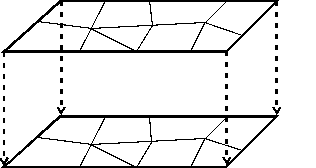
All 3D elements have the same “floor plan” based on the 2D mesh. The system for assigning node and element numbering enables quick identification of all elements and nodes based on the 2D mesh plan:
The starting point is the 2D mesh of a horizontal model.
All nodes in the various 3D layers at the depth have the same x and y coordinates.

To simplify mesh generation, it is advisable to decouple planar and spatial mesh generation. Firstly, a 2D finite element mesh is generated, as with a horizontal plane model. Care must be taken to ensure that all constraint points such as abstraction wells and measurement levels or layer boundaries are also taken into account in depth. In a second step, this 2D mesh is projected vertically.
Starting from an existing horizontal model has two advantages: When creating a 3D model, it is easier and clearer for the user to first complete a 2D model as usual and test it for input errors.
In the case of existing models, this procedure allows a quick extension to the third dimension if, for example, it turns out during calibration or the simulation calculation that a horizontal model is not sufficient to reflect the real conditions.

Data processing
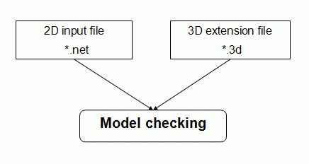
The generation of the mesh in depth, which is controlled via the supplementary file of the 3D data, takes place during the model check. The projection of the horizontal mesh onto deeper layers allows an automated procedure with very little additional input. In principle, two methods are possible:
3D expansion via number of layers and partitioning (3DSH)
3D extension via specification of Z-coordinates (ZKOR)
 3D expansion via number of layers and division (3DSH)
 3D extension via specification of the Z-coordinates (ZKOR)
