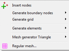
In this chapter all menu items and processing steps are briefly described. Then the algorithms of node generation are described in detail. The following menu items are available

Insert nodes
At any point nodes can be created with the left mouse button.
Generate boundary nodes
The algorithm is described in chapter: Algorithm of the boundary node generator.
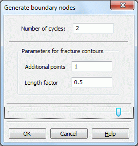
In the first step of each mesh generation you should generate nodes at all contour nodes and perpendicular to the contour lines. This can only be done if a closed contour boundary exists. Hence, the function Generate boundary nodes (Global... or Area) starts with a computation of the contour boundary. Only for the case that the contour boundary has been computed successfully does the following menu appear. In this menu, you must define the number of generation steps (n):

For projects without any fracture contours only the Number of cycles is required. Inserting n=0 means the algorithm passes only step 0 of the boundary node generation and generates nodes directly at contour nodes. Inserting n >0 means the algorithm generates nodes directly at the contour nodes plus n nodes perpendicular to the contour line.
For projects containing fracture contours two further parameters are required. The Length factor is used to decrease the distance between generated nodes along fractures. The number of Additional points controls the discretization perpendicular to the fracture. The boundary node generation algorithm generates the nodes perpendicular to the fracture with a distance which is exponentially increased in each step.
Area…:
Is the computation of the contour boundary successfully, the area where the boundary nodes are to be generated can be defined. It should be ensured that all existing nodes are captured in the definition of polygon for the node generation.
Notes:
It is recommended to start the boundary node generator at least with the 0th. initialization step because problems in the mesh generation occur if there are no nodes on contour nodes. Moreover, depending on the model 1-2 cycles of boundary node generation are recommended.
If in an area a large number of generation cycles is necessary the following approach is recommended:
First, the boundary node generator performs a small, global reasonable number of generation steps. In a second step, all nodes in the area where more generation steps should be performed are deleted.
Thereafter, the boundary node generator performs a greater number of generation steps. In this case, no new mesh nodes are generated from contour points that lie outside the deleted region. That is, even the 0th step of the boundary node generator fails because of the termination criterion "mesh node in the vicinity already exists" and thus no other generation steps are carried out from these points.
Generate grid
The algorithm is described in chapter: Algorithm of the grid node generator .
A global grid generation presumes that a closed contour boundary exists. Hence, the function Generate grid (Global.../area) starts with a computation of the boundary contour.
If the grid should be generated in an area this area has initially to be defined. In defining the polygon for the generation edge, make sure that all the existing nodes are included.
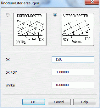
Only for the case that the boundary contour is computed successfully does the following menu appears:

The nodes are generated so that the resulting triangles or quadrangles are as close to equilateral as possible.
The default type is a rectangular grid, a triangular grid requires due to the higher number of elements only a higher storage and computational effort.
The default value DX is obtained from the average length of the contour lines along the outer contour boundary (without considering the intermediate nodes) scaled with 0.3.
The default ratio DX/DY is obtained by the ratio of scales in the directions x and y defined for the project: Usually, the scales in the direction x and y are identical for 2D horizontal and 3D models. Then the default ratio DX/DY=1 leads to the generally favoured regular grids. In case of vertical models, the scale in the y-direction is often super elevated compared to that in the x-direction. Then the resulting ratio DX/DY>1 leads to the generally favourable rectangular grid with long horizontal and short vertical edges.
By entering an angle the element edges are rotated against the horizontal.
By confirming the menu with OK the specified grid is generated. The point of origin of the grid is assigned to the minimum x- and y-coordinates of the boundary contour.
Using this menu is described in detail in the tutorial: Step 2, generating nodes.
Generate elements
With SPRING the elements of an FE mesh can be created in different ways. Models can be created only with triangular elements or they can be created with triangular and quadrangular elements.
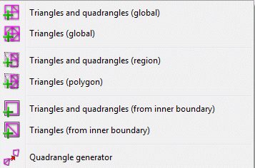
Therefore, the menu item Generate elements has the following submenu:


Generating Triangle, Triangles and quadrangles (global/region/from inner boundary):
After inspection of the closed contour boundary and any definition of the region/inner boundary, the Triangulation starts.

All existing elements which were completely inside the specified boundary are deleted, including their attributes.

All nodes inside the specified boundary are triangulated considering all contour data completely inside the polygon.

For the generation of triangles and quadrangles, triangles which are suitable for this purpose are combined to quadrilaterals after the triangulation.

The menu items Triangle and quadrangles i.e. Triangles (region) are to be used for the manual generation of elements as well.
The mesh generator uses the polygon segments as element edges! The triangulation takes more time if there are more nodes and contours which need to be considered

Quadrangle generator:
By using this function you can combine suitable triangles to quadrangles afterwards. Please notice that by doing this, the attributes of one of the triangles will be lost.
Mesh generator Triangle…
Using the mesh generator Triangle is described in detail in chapter: Using the external mesh generator Triangle .
Regular mesh…
Generating a regular mesh is described in detail in chapter Compilation of a 2D model: Generating an FE-mesh with automatic mesh generation .
 Algorithm of the boundary node generator
