A path line is the line that describes the path of a water particle over a flow time t. Trajectories are calculated by tracing the path of an imaginary water particle through the flow field. The derivation of the potential heads results in the filter velocities, which are converted into distance velocities using the following equation:
va = vf / nd
with
va = distance velocity
vf = filter velocity
nd = flow effective pore volume
Two things play an important role in the accuracy of the lines:
Since a constant velocity is calculated for each element (with a linear approach for the potential heads), the discretisation of the model area must be correspondingly fine in areas with changing gradients.
A smooth transition must be ensured for the interpolation between the element centres.
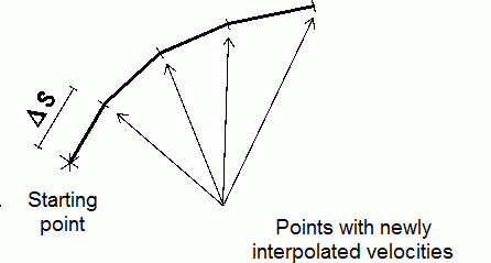
In the practical calculation, the trajectory is tracked for a certain distance (s) at the initial speed, then a new speed is interpolated and tracked further. The path sections must be selected by the user depending on the inhomogeneity of the flow field.

Calculation of a path line
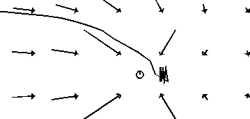
The extraction wells are a problem area in the calculation of path lines. If this fact is not taken into account as a secondary condition, the changing flow directions result in overshooting zigzag lines:

Path line calculation on a well without secondary condition
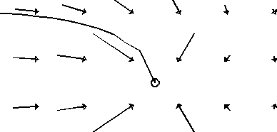
Better results are achieved if you check instead whether the newly calculated path line particle is close to a production well. If this is the case, the path line can be "trapped":
The path line tracking ends when one of the following criteria is met:
a specified time or distance is reached,
the edge of the modelled area or an open water area is reached,
the path line is "captured" by a node with a withdrawal rate,
tthe distance between two consecutive path line particles falls below a specified limit.
The implementation and the required entries in SPRING are explained in the chapter "Calculating and displaying path lines".
The starting points for path lines can be located around nodes, in element centres or at any coordinates x, y, (z). The direction of the path line tracing can be selected in the direction of flow or in the opposite direction. The second option is useful for determining a protection zone around a well (e.g. 50-day limit). The following can be specified for the path lines in the input dialogue of the plot creation time markers can be set, which can then be used to manually construct isochrones.
The calculation of transient trajectories differs only in that the velocity field changes at each time step. In addition to the trajectory sections s, it is therefore checked that the tracked flow time t is not greater than the time step length T.
 Calculating and displaying path lines

