All input data is stored in the structural data. However, not all structural data are automatically constrained geometries for the FEM mesh. For example, measuring points or geological outcrops located outside the area under investigation do not represent constraint geometries. Only the constrained geometries of the structures are transferred to contours (Contour  New From structure).
Editing the contours provides the basis for a homogeneous FE mesh. When transferring the structure to a contour, a contour point is created at each structure point, and a node will eventually be created at each of these positions during mesh generation. Therefore, the distances between the structure points must be taken into account when transferring the structures to contours.
The individual structure points can therefore be made visible in the structure menu by activating the Show markers option in the edit structure dialogue.
In the example structures, the distance between the structure points of the north-eastern edge is sometimes very small. Therefore, not all structure points of the north-eastern edge should be adopted as contour points.
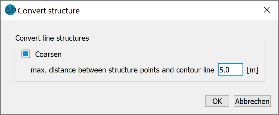
The distance between the contour points is coarsened via Contour New From structure (Pick, List…, or All) and the following input window then appears. The maximum distance between the points and the contour line is set to 5 metres:
Convert l-structure
To create a regular distribution of the edge nodes, go to Contour Edit L-contour Define maximum distance Polygon, and draw a polygon around the northeastern boundary contour. The distance between the contour points should be set to a maximum of 300 metres. This corresponds approximately to the distance between the structure points of the south-western edge.
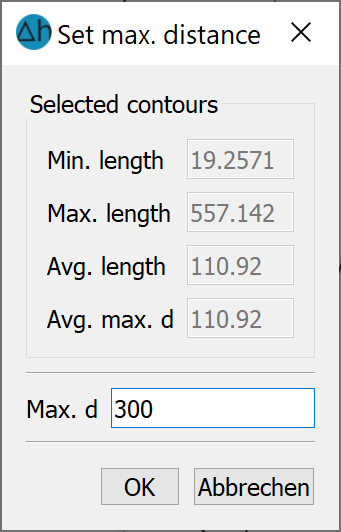
Setting the maximum distance
The same procedure is recommended for the lake, but here the distance between the contour points should be smaller (approx. 35-50 m) in order to obtain a smaller element edge length later.
The other structures (stream, fountain and the south-western edge of the model) are created with Contour New From structure Pick / List... as contours without coarsening. When selecting List, it is possible to convert several structures simultaneously by pressing the CTRL key and selecting the desired structures at the same time.
The distance between the points can be reduced for individual contour elements at the south-western edge of the structure and along the stream. This is done via Contour Edit L-contour Define maximum distance Pick. The contour elements that appear "too large" to the user are now selected. An input window appears in which the desired maximum spacing can be entered.
At the point where the stream flows into the main receiving watercourse, the neighbouring contour of the main receiving watercourse must be divided once (Contour Edit L-contour Divide n-times: 1) so that the contour point of the stream can join the division point (Contour Move points).
To finalise the changes to the number of nodes in contours via the define maximum distance method, click on the Contour Edit L-contour Split at segmentation points (Pick, List…, or All). This will add the new proposed points to the line contours.
The result is the contours shown in the following illustration:
Existing contours
For a better representation of the logarithmic sink funnel around a production well, it is necessary to assign corresponding well parameters to the contour points of the wells. This prevents oscillations caused by the punctual change in potential near the well. After editing the Contour Edit P-contour Well parameters Pick and clicking on the three points, confirm with a click of the right mouse button and the following input window appears:
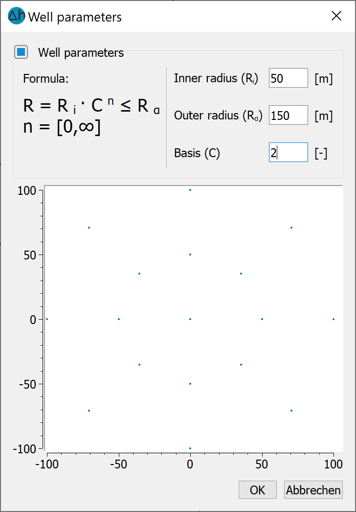
Define well parameters
Assign the parameters as in the screenshot above. A detailed description of the parameters can be found in the chapter Description of the data types: Spatial discretisation: Special case of well discretisation".
Before creating nodes, you must check whether the contour boundary is closed and the distances between individual contour points are not too small. This is done via Contour Optimise. The setting of the accuracy parameters is confirmed with "OK". If the check is error-free, a message appears with the comment "Contour boundary closed". If errors occur, these are displayed and must be rectified by changing the accuracy parameters.
Note: The following also applies to the contours: when reopening the project, the contours must be displayed via View Contours, in the Project manager or via the corresponding button ( ).
).
The next step is Creating nodes
Stand: 06.05.2025 | 