The mesh menu is only available in the model mode. The following menu items are available:
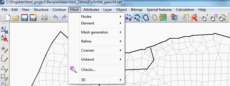
Nodes
The position of the nodes

can be edited.

Move  nodes:
By using this function, you can change the position of an existing node directly with the help of the cursor. The node can be moved to a free coordinate (Freely) or to an already existing point (Capturing mode) by pressing the left mouse button. When moving nodes, the user should always take care of the affected elements. He has to avoid moving nodes into inadmissible elements.
By using Edit  Undo or selecting the button
  the moving is undone.
Moving the nodes, does not change the node attributes at all. Depending on the attribute, it can be necessary to assign a new value to the node afterwards. Moving a node by several metres can require a new interpolation of the ground level or the receiving water course level.

Merge nodes:
In many cases two nodes which are too close to each other and could be merged are not visible until elements are generated between the nodes. The second case where the function Merge can be quite useful is the merging of two separate models which have a shared boundary. In these cases, the function provides the following steps:

Both nodes are moved to their geometric centre by changing their coordinates.

The node attributes existing at both nodes are averaged (except inflow / outflow rates KNOT).

One of the nodes is deleted.

The incidences of the adjacent elements are corrected.
The two nodes to be merged are selected by one of the following methods:

Capture two: Two nodes are chosen with the left mouse button.
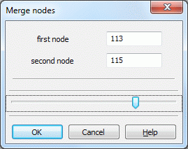
Two by numbers...: An input window appears in which the two numbers are entered:
According to distance...: An input window appears in which the maximum distance in x- and y-direction is entered:
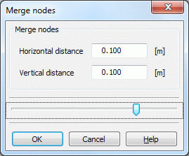
In case of a super elevated vertical model, the distance in the x-direction should be larger than the one in the y-direction. All nodes whose distances are smaller than the entered values are merged automatically by SPRING, they are coloured and displayed in the main window.

Delete nodes:
The following submenu appears:
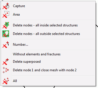
The nodes can be deleted manually (Capture), inside a polygon (Area), inside or outside selected structures or by number.
By selecting the menu item Number… appears an input window in which the number of the node to be deleted is entered:
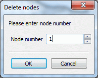
It is also possible to delete nodes which do not belong to an element or a fracture or whose coordinates are equal to another node (Delete superposed).
Attention! If a node is deleted, all adjacent elements of the node are deleted automatically.
The menu item "Delete node 1 and close mesh with node 2" allows the user to delete a node (node 1, by selecting it with the left mouse button) by moving it to and merging it with another node (node 2). In this process, no elements are deleted. Node 2 can be selected with the left mouse button, or, by pressing the right mouse button, the closest node is automatically selected by the program. The element and node attributes donot change.
Element
In the submenu Mesh  Element
  Delete are different possibilities available to delete one or more elements:

The elements can be deleted manually (Capture), in an area or by number.
By selecting the menu item Number… appears an input window in which the number of the element to be deleted is entered.
By selecting the menu item With filter… an input window appears in which an item can be deleted based on its attribute value:
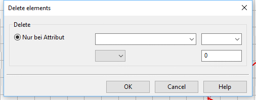
When deleting elements based on selected structures only those elements are deleted whose nodes and element center are completely inside or outside the structure or on its edge.
Note to the menu item Element  Delete
  All with wrong orientation:
The element generation in SPRING is generally counter-clockwise. If the user has inadvertently created elements with the wrong orientation by editing the model file, he can automatically delete them here.
Via the menu item All all elements are deleted!
Mesh generation
Since this menu item is very complex, it is treated in a separate chapter.
Refine
The following submenu appears:
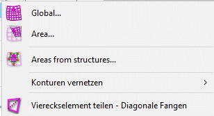

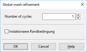
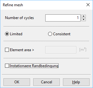
By activating the function Global…, the following window appears:

If Area… or Area from structures is selected, only the elements in these areas are refined. The procedure corresponds largely to the global refinement. In refining an area a minimum element size can also be specified. The region between the refined and the non-refined elements must also be edited. For a good transition from the refined to the non-refined region, some elements outside the specified polygon must be refined. There are two different strategies to do that:

Interlinking contours:


Divide quadrangle element - select diagonal
By using the function "capture diagonal", you can divide a quadrangular element along its diagonal into two triangles. The corresponding corner nodes are captured with the left mouse button. The new elements get the attributes of the former element.
Coarsen
The coarsening can take place globally, by area or individually:

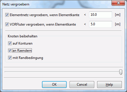
With a global coarsening, another window appears, in which the corresponding criteria are selected:
Unbend
Unbending the mesh can be done globally or regionally:

When using various mesh-generation algorithms, regions with different grid distances and manually-generated regions, the transition between the corresponding meshes can be abrupt. By using this function, you can smooth these transient regions globally or in a polygon (selecting the desired area with the left mouse button). The algorithm automatically moves nodes to achieve the best mesh geometry. You must define how many times the algorithm should smooth the mesh (see also Unbending the mesh):
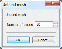
The larger the number of cycles chosen the larger is the influence of the smoothing algorithm in the transient regions into the regions with generated grids. Furthermore, the algorithm moves the nodes around wells (contour points) which were generated logarithmically from well parameters.
Nodes and element edges which lie on or along contours are not moved.
Checks…
The mesh generation should be completed with several geometry checks before any data are assigned to the mesh. Errors in the mesh geometry can lead to the finite element calculation not being able to start. By activating this function, the following window appears where the different algorithms can be selected:
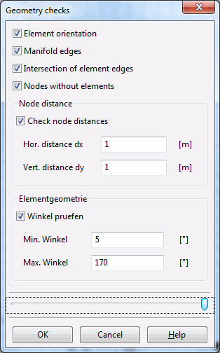
The algorithm Element orientation checks whether the nodes in each element are oriented anti-clockwise. Elements with a clockwise node list (resulting from manually picked elements) have to be deleted and selected again counter-clockwise.
The algorithm Manifold edges checks whether any element edge exists too often: element edges exist at most twice. At the mesh boundary, element edges exist once, while in the interior, element edges exist twice yet with different directions. Multiple edges are caused by multiple elements or wrongly-oriented elements.
The algorithm Intersection of element edges checks whether any element edge intersects with another one. (For a large mesh, this can take some time.)
The algorithm Nodes without elements searches for nodes which do not belong to any element.
The algorithm Node distance helps to find nodes existing twice or nodes very close to each other. Nodes where the distance of the x-coordinates is smaller than DX or rather the distance of y-coordinates is smaller than DY produce an error.
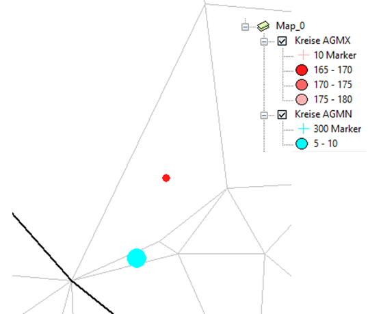
The control of the element geometry helps to detect elements with poor quality (with very small or large angles). First, a corresponding error message appears:

The minimum (attribute AGMN) and maximum (attribute AGMX) angles are stored as attributes AGMN and AGMX and can be displayed after the mesh control:
3D
Since this menu item is very complex, it is treated in a separate chapter.
