(This menu item is only available when the model file is open) The following menu items appear:
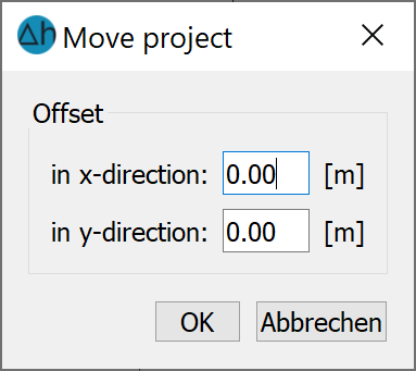
Move 
Allows you to move the origin of a model, e.g. to switch from relative (x, y) coordinates to Gauss-Krüger coordinates. The offset in the x and/or y direction must be entered in the dialogue box.
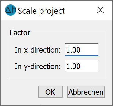
Scale 
This menu item can be used to scale a model, i.e. the distances in the X and/or Y direction can be increased or decreased using a factor. The factor for scaling in the x and/or y direction must be entered in the dialogue box.
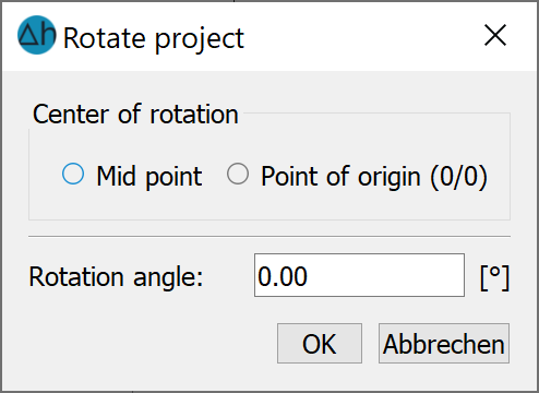
Rotate 
This menu item can be used to rotate the coordinate system of a model. You are expected to enter a rotation angle in degrees. Please note that rotation is counter-clockwise).
Set projection
This menu item can be used to set the coordinate reference system. The following input window appears:
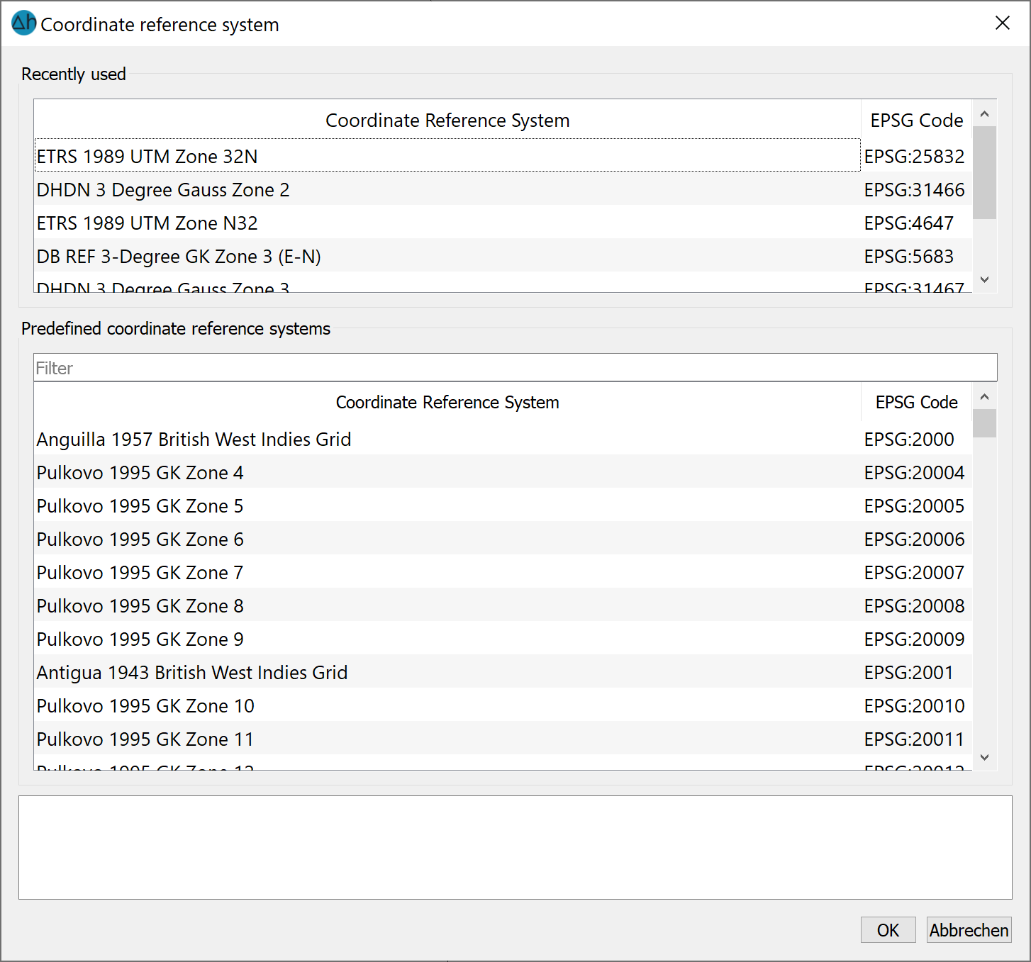
Specifying the coordinate reference system makes it possible to load supplementary maps from Google, OpenStreetMap or other geospatial layer providers directly into the current model. This is done by navigating to the Add layer  XYZ Tileserver or the Add WMS layer menu. The selected coordinate system is saved in the model file (*.net). Changes can also be made to the coordinate reference system in the Project information window using the right mouse button.
Adjust numbering 
The following input is possible:
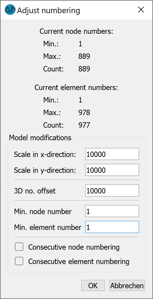
Scale in x-/y-direction
This menu item can be used to change the scale of the model file in the x and/or y direction.
3D-no.-offset (3D model only)
This menu item can be used to increase or decrease the 3D number offset (3DNR) for a 3D model. If an enlargement is necessary when creating/refining the model, the 3D offset is automatically adjusted.
Min. node-/element number
All node numbers and/or element numbers can be modified by a specified offset by changing the minimum node number or the minimum element number. The node and element numbers must remain positive (when offset downwards). An offset that may no longer be suitable for 3D numbering is automatically changed.
This function is mainly used to prepare two individual models for coupling
Consecutive node/element numbering
Gaps in the node and element numbering often occur during mesh generation and modification. This can, for example, lead to the standard 3D offset of 10000 becoming too small, as node and/or element numbers greater than 10000 have been created, although fewer than 10000 elements and nodes are actually present. In these cases, it may make sense to renumber the nodes and/or elements to consecutive numbers.
Stand: 06.03.2026 | 