The line display type is not freely selectable, but is the default for the display of the mesh boundary, node and element numbers, markings, as well as velocities and 2D fractures..
Mesh (batch command NETZ), Mesh boundary (batch command RAND)
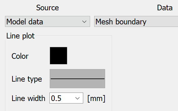
The colour, line type and line width can be freely defined for the mesh and the mesh boundary.
The colour and size can be set for the plot output of element numbers or node numbers.
Markers (batch command MARK)
A colour, a line type and a line width can be selected for the markings in the model. In a 3D model, the markings are displayed in the layer selected above.
Velocities (batch command GESC)
When displaying the velocities, the colour, line type and line width can be freely defined.
If velocities of a 3D model are to be displayed in a vertical section, the following input block appears:
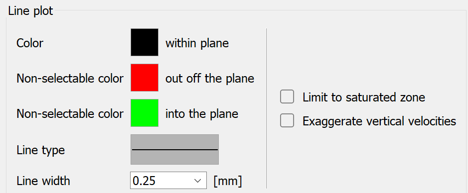
In a vertical section through a 3D model, the velocity arrows are always displayed in three colours. If the direction of the resultant of the velocity components does not deviate more than 20 degrees from the section plane, the first colour is used (in the plane). If the resultant points out of the section plane, the second colour is used. If the resultant points into the plane, the third colour is used.
The first colour can be selected by the user. The other two colours are assigned internally by the programme and are displayed here for preview purposes.
2D fractures (batch command KL2D)
The colour, line type and line width can be freely defined for a 2D fracture. Example of 2D fractures in a 3D model:
2D vertical section of fractures
 Isoline
Stand: 02.06.2025 | 