The boundary of the 3D area is first defined in the existing model. The new 3D boundary is automatically assigned with Mesh  3D 3D Boundary Mesh boundary = 3D boundary. The model type "3D model" now appears with the properties of the project via View More windows Project information.
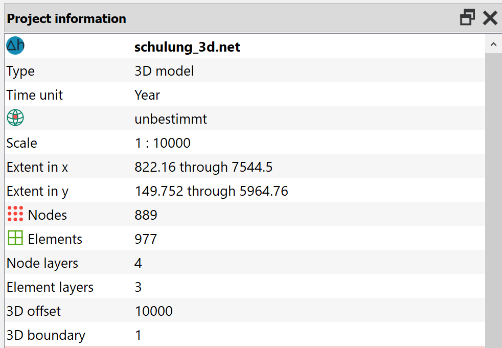
Project information
After selecting Mesh 3D New layer arrangement…, the following window appears in which the desired arrangement can be defined:
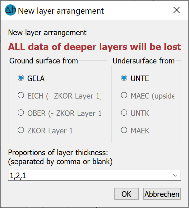
New layer arrangement
In the lowest field, the number and thickness of the element layers are defined according to the geological conditions.
The numbers given in the example have the following meaning:
The amount of numbers (For this exercise we will have 3) determines the number of element layers.
The sum of the numbers (For this exercise: 1+2+1=4) determines the partial thicknesses of the individual element layers. In the example, the existing thickness (= upper edge of the terrain - lower edge of the model) is divided by 4 and multiplied by the specified ratios of the individual layers. This results in a layer thickness of 1/4 of the total thickness for the first layer, a layer thickness of 1/2 for the second layer and a layer thickness of 1/4 of the total thickness for the third layer.
The following vertical section clearly shows the relationship between the layer thicknesses:
Vertical section of the new 3D model (100-fold exaggeration in the Z direction)
It is already possible to view a section through the model during mesh editing in SPRING. Via View Vertical section, select any two points (press the left mouse button) that define the corresponding vertical section through the model. This feature is independent of the model type, it also works with horizontal models.
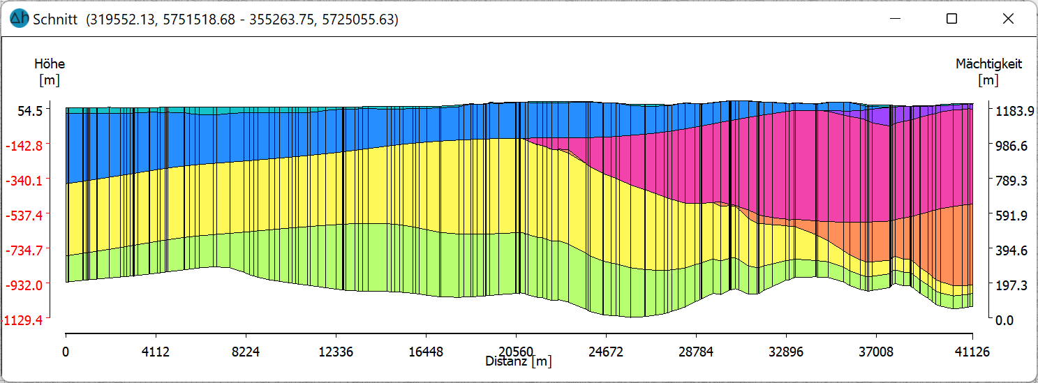
A vertical section through a 3D model
The layers of the 3D model can be displayed via View More windows 3D view. Another window (3D view) opens in which the model can be rotated in any direction by pressing the left mouse button:
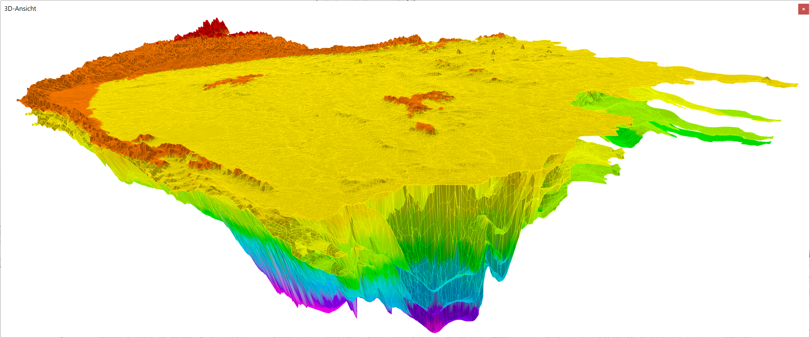
Three-dimensional view of a model
For a simple flow calculation, it is sufficient to use Attributes Assign Direct... to assign K-values to the lower layers. In the case of complex hydrogeological conditions, a layer-by-layer calibration may have to be carried out for deeper layers or aquifers and further necessary attributes introduced (saturation parameters, impermeable layers, etc.).
3D extension via specification of the Z-coordinates (ZKOR)
Stand: 22.01.2025 | 