For better clarity in the later plot representation, the abstraction wells are assigned the "120" markings (which is the typical well marking), as follows:
Via View  Show attributes Attributes… or the Isolines/area plots/values toolbar button and then select KNOT, the abstraction wells are displayed. The new marking can be assigned to them via Attributes Assign Direct...: MARK = 120 the corresponding marker can be assigned by selecting Single assignment option and clicking on each abstraction well node.
The assigned markers can be displayed via View Markings, or the corresponding button in the toolbar ( ) can be activated.
Groundwater recharge (FLAE) and hydraulic conductivity (KWER) are still missing for the subsequent flow calculation. These data types can be assigned to all elements across the entire area with Attributes Assign Direct. In the example, the groundwater recharge for the entire area is assigned to all elements.
The attribute must be set to FLAE and the value as 0.20, with the " * " sign in the Token box, which corresponds to a recharge rate of 0.200 m³/m²/time unit or 200 mm/year.
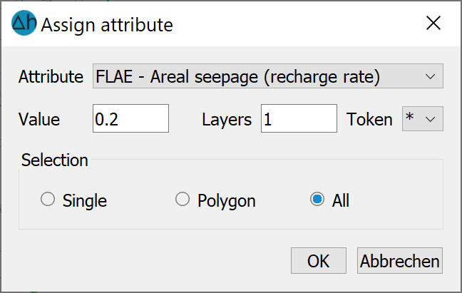
Assigning attributes directly
The same is now done for the determination of the hydraulic conductivity values (KWER) of the entire model area, but without an additional character in the Token box. The initial K-values are set to 0.00005 m/s. In addition, an upper (KMAX = 0.002 m/s) and a lower (KMIN = 0.000001 m/s) bound for the later calibration are introduced for the K-values, which must also be assigned to all elements.
The mesh created up to this point, including the structure data file "s3_schritt3_3.zip", can also be found at this point in the directory /Tutorial_bsp_files/Tutorial_2D_bsp_files/s3_schritt3_3.zip.
Now that all the data required for calibration is available, the calibration process is explained in more detail in Step 4: Calibration of a groundwater model“.
Since all data required for calibration are now available, the calibration procedure is illustrated in more detail in step 4: Calibration of a groundwater model.
Stand: 06.05.2025 | 