Structures contain data i.e. values at the points of the structures beside the geometry information. These data, combined with the structure identifier, can be assigned to nodes and elements of the mesh.
First, the structure must be specified via Capture or List…
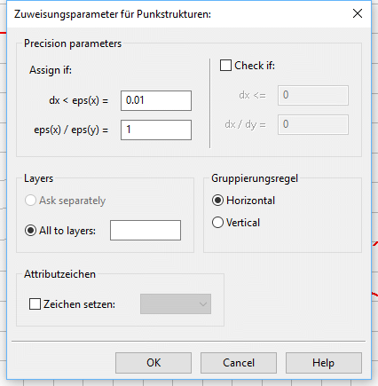
Then an input window appears, in which the assignment parameters are defined:
For point structures:

Meaning of the dialogue entries:

Assigning point structures:
In case of nodal data, the node must lie within the specified distance dx < eps(x) from the structure point. Then the value (if existing) is assigned automatically. In case of elemental data, the element centre must lie within the specified distance dx < eps(x) from the structure point.
If the ratio eps(x)/eps(y) is equal 1, the structure data are assigned to all nodes or element centers within a circle of radius dx around the structure point. However, the distance dx <eps (x) = 60 m and the ratio eps(x)/eps(y) is set to 10, the structure data are assigned to each node or element centers within an ellipse with a semi-axis x = 60 m and y = 6 m around the structure point. If the distance dx <eps (x) = 60 m and the ratio eps(x)/eps(y) is set to 0.1, the structure data are assigned to each node or element centers within an ellipse with a semi-axis x = 60 m and y = 600 m around the structure point.
If the check if is activated a tolerance limit can be determined. That means, the nodes or element centers that have a slightly larger distance than dx to a structure point, get the structure data anyway after a query.
For 3D models, the node or element layer is to be specified. It is possible to specify several layers at once (layer numbers separated by comma or semicolon or joined by a hyphen). The data can be grouped immediately horizontally or vertically.
Depending on the data type, the appropriate attribute character can be assigned immediately.

Assigning line structures:
The dialog corresponds to the point structure assignment, except for the point-specific properties.
Assigning line structures makes only sense for node wise data. There must be at minimum one value defined at a point of the structure line.
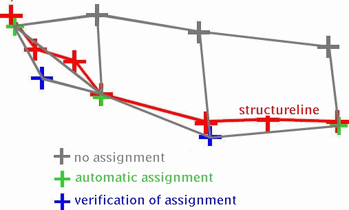
All nodes which are according to the distance definition above are close enough to the line structure get automatically a value of the relevant structure data.

Assignment of structure lines
Depending on the type of data a different assignment is used:

In case of individual values, the value is linear inter- or rather extrapolated.

In case of data along polylines and group data, all nodes receive the first value of the line structure.
Attention: The assigning of data along polylines or group data (e. g. LERA, MXKI or BILA) always uses only one value. Therefore, different values along the structure line are possible but not useful. For the representation of a receiving water course with several segments with different LERA values, different structures must be used.

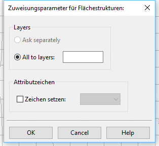
Assigning area structures:

Area structures can only be assigned to single-valued data and group data. Each node or element centre lying inside or at the boundary of the area structure automatically receives a value. There are no distances defined or verifications of assignment, as there are for line or point structures.
The assigned value at the appropriate node results as follows:

In case of group data, all nodes or elements receive the first value defined at a corner of the area structure.

In case of single-valued data, the first three values defined at corners of the area structure are used for the definition of a skew plane. The final value depends on the position of the node / element centre in the plane. If there is only one corner with a defined value or the first three values found are equal, a constant value is assigned. For more than three values, the remaining ones are not significant for the assignment. If there are only two values, the second value is not interpreted and the first value is assigned as a constant.
Attention! The assigning of group data (e.g. BILA) always uses only one value.
Attention! The assigning of area structures to single value nodes or elements uses a maximum of three values. Thus more than three different values at the corners of the area structure are possible yet not meaningful.
The proper assignment of polygon- and group data can be examined via Attributes  Special Features
  Check group attribute respectively polygon line attribute. If the generated attributes overlap with existing attributes of the same type of data, the affected attributes are displayed as green lines and the conflicting nodes with green circles.
