The special features menu is only available in the model mode. The following menu items are available:

Water course systems
In SPRING is an integrated network of water-related systems available in order to consider the exchange processes between surface water and ground water. This tool is available for steady state and transient problems in a 2D or 3D model.
The network of water-related systems determines the groundwater dependent runoff also about the deeper layers along the flow direction. This requires the definition of water course systems in the deeper layers, but not the parameters "wetted perimeter", "Manning-Strickler coefficient", "slope" or "gradient".
To use this interaction between surface water and groundwater it is necessary to ensure that a clear direction of flow and the link of the water branches are given.
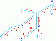
Even if a derivation of water levels (VORF data as a result) in deeper layers is technically possible, this is not provided, because the layer height of the node layer is considered. It makes sense, therefore, the definition of the water course systems is assigned to the top layer.
Attention:

A multiple assignment of water systems and water system-related parameters should be avoided, since there is no attribute check.

A water system can only lie in a single node layer, it cannot partially change the layer.
The following functions are selectable in the submenu:
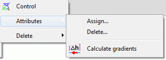

Control 
A check on the accuracy of the flow direction of the water systems takes place. Due to the conservation of mass flows at each node exactly one water stream flows away from one node and any number may flow to the node.
The separation of a water in two opposite flow directions results in an error message.

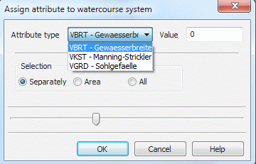
Attributes assign/delete
An input window appears in which the water system attributes can be defined and assigned to nodes.
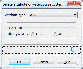
The following window appears when activating the menu item Delete:

Calculate gradients 
After selecting this function, a dialog window appears where the user can choose whether the slope gradient is calculated from the receiving water course level or the ground level.
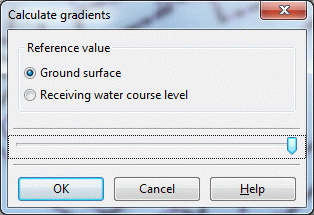
The attribute VGRD is calculated for all water course systems (unit: promille). After saving the project the attribute is stored in the model file.
The gradient (corresponding to the bottom slope) is determined by the ratio of the difference of the ground surface or receiving water course level to the distance between adjacent nodes along the element edge. In the menu View  Show attributes
  On watercourse systems... the gradient direction on the element edges can be displayed as arrows by selecting the attribute VGRD.

Delete
If water course systems are available, they can be deleted individually, or in an area or completely, because they are stored as a separate layer.
Transient
Fractures
If fracture contours are present (chapter: “Generate fracture contours“), the following functions are selectable in the submenu:
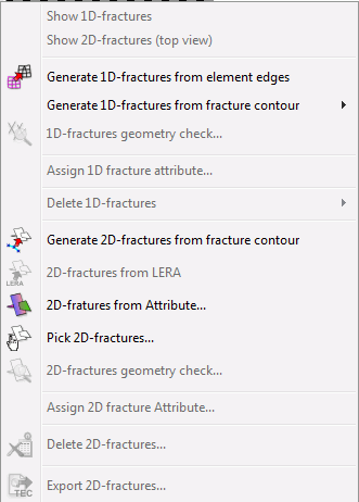

Display 1D, 2D fractures
When available, the fractures are presented.
Example of a 2D fracture (direction of incidence: 280°):
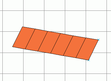
Top view of a 2D fracture (direction of incidence 280°)

Generate 1D-fracures from element edges 
The following input window appears:
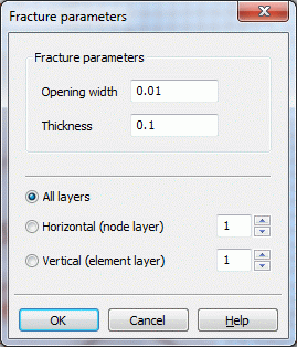
After selecting a layer or all layers fractures can be created along the horizontal or vertical edge of elements. The fracture parameters have to be set.

Generate 1D or 2D fractures from contours 
Only when choosing this menu item, the previously generated K-contours are imported as fractures in the model. The appropriate entry in the project information window (1D-fractures:.. or 2D-fractures: ...) shows this. The 1D-fractures can be captured, selected in an area or selected all (previously the contours have to be represented). The 2D fractures can be selected manually (previously contours represent).
Via View  More windows
  3D-view the fractures are displayed in space.
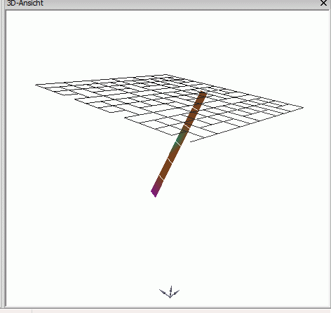
2D fracture with angle of incidence 85°

1D- 
![]() , 2D fractures geometry check
, 2D fractures geometry check 
When activating these functions, the system checks if the fractures intersect. This is currently technically not possible.

Assign 1D or 2D fracture attribute...
An input window appears:
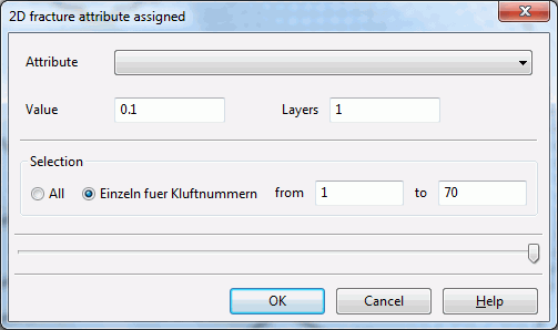
Attributes are assigned to fractures with the help of this input window.

Delete 1D-fractures
The 1D-fractures can be deleted manually by capturing, they can be deleted in an area or all at one time.

2D-fractures from LERA 
This menu item contains the function "Lera2Kluft" which previously was only available as a Python script. The menu item is only active when the data type LERA is available in the model file. The operation is described in chapter: “Creating a 3D model”.

2D fracture from attribute...
The following input window appears:
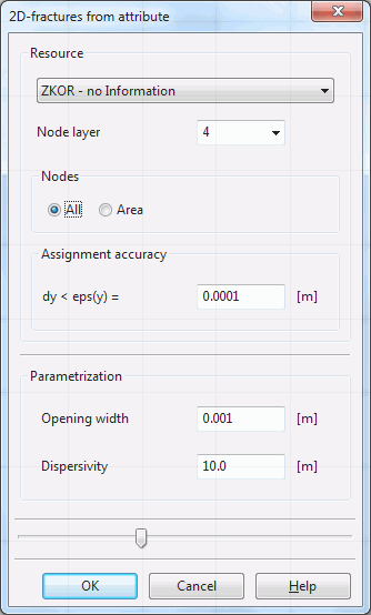
2D-fractures are generated from existing attributes.

Pick 2D-fractures 
This menu item allows the user to create vertical or sloping fractures via the user interface. The following input window appears:
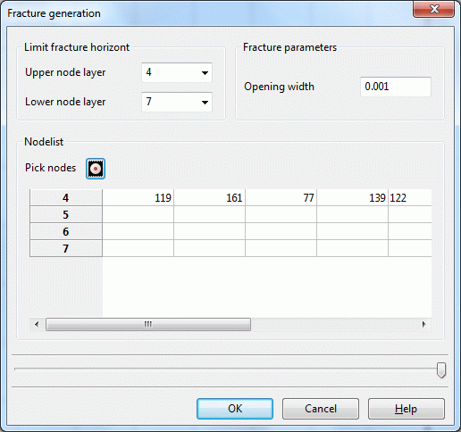
The upper and lower node layers of the fracture as well as the fracture opening width are defined in this input window. In the node list, the fracture nodes are defined manually or interactively through the user interface. The following figure shows a group of fractures thus created:
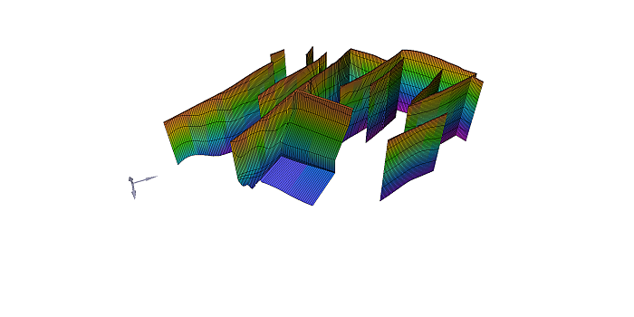
Example of a group of fractures, made up of vertical and sloping fractures
This menu item allows the user to delete all fractures. There is also the option to delete 2D fractures selectively either on the edge length or the area. The following input window appears:
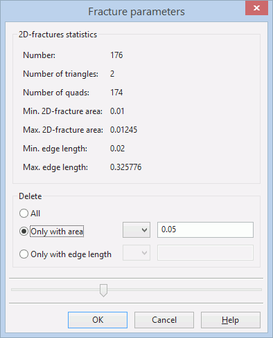
After confirming with OK is in the status bar at the bottom of the screen displayed, how many fractures were deleted with the appropriate feature.

Export 2D fractures 
A file selection window appears in which the export file for the program Tecplot is defined.
