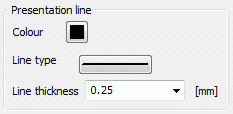
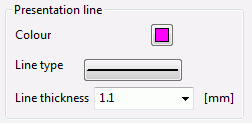
The illustration type XE "illustration type:line" line is not selectable, but set by default for the presentation of the mesh boundary, the node and element numbers, the markings, velocities and 2D fractures.

Mesh boundary (batch command RAND)

The colour, the line type and the line thickness are freely defined.

Element numbers, node numbers (batch command KNNR , ELNR)
The colour and the size can be defined.

Markers (batch command MARK)

This check box is only available in 3D models.

Velocities (batch command GESC)
When displaying the velocity, the colour, line type and line width can be freely determined.


2D fractures (batch command KL2D)

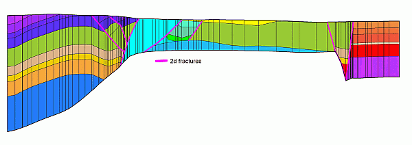
The colour, the line type and the line thickness are freely defined. Example of 2D fractures in a 3D model:

2D fractures in a vertical section

 Contour line