For realising a partial 3D model in SPRING you have to define the boundary of the 3D part first with Mesh  3D
3D  3D-boundary
  Generate. All boundary nodes have to be captured.
After confirming the boundary with the right mouse button the new layers have to be arranged (see 3D-Enlargement by the definition of the number of layers and proportion factors (3DSH) ).
Here the partition factors "1, 3, 2" were defined. Resulting are 3 layers with a partial thickness of 1/6, 1/2 and 1/3 of the entire thickness.
With View  3D-boundary you can display the new 3D-boundary. Because the predefined way of representation is not very obvious change it with the Object toolbar (View
  Toolbars
  Object attributes). Change the colour and line width and assign them to the object.
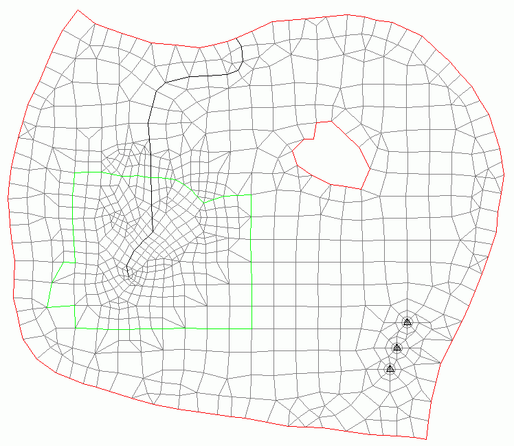
You get the following figure:

Displaying the 3D boundary in SPRING
At least, the permeability (KWER) has to be assigned to the new generated elements to run a flow computation.
Besides after running the model checking it is possible to display the modified model with File  Plot generation
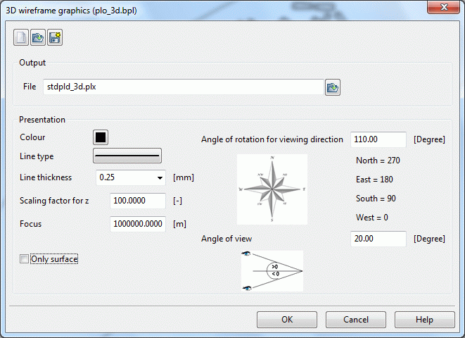
  3D wireframe. The following input parameters were defined:

Input for a 3D wireframe
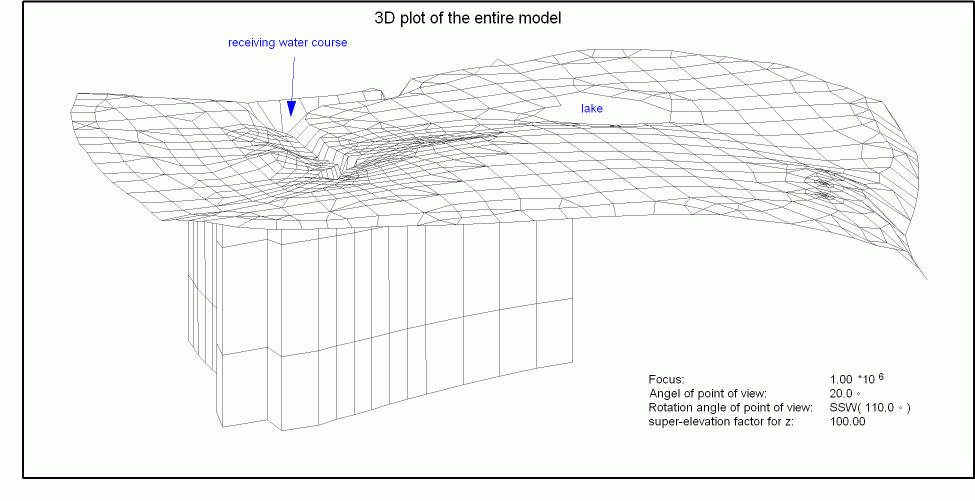
The following figure of the partial 3D model results:

Mesh plot with partial 3D area
