SPRING provides an integrated network of watercourse systems for the supply-wise consideration of exchange processes between surface water and groundwater. This tool is available for steady state and transient problems and for 2D or 3D problems.
The watercourse system also determines the groundwater-bearing flow (discharge volumes) via the deeper layers along the flow direction. This requires the definition of the watercourse systems, but not the channel parameters "width", "Manning-Strickler coefficient", "slope" or "gradient" in the deeper layers.
To utilise this interaction between surface waters and groundwater, it is only necessary to ensure that the flow direction is clear and that the watercourse branches are connected.
Even if it is technically possible to derive water levels (VORF as result data) in deeper layers, this is not intended, as the height of the nodal layer is taken into account. It therefore makes sense to set the definition of the water bodies to the uppermost layer.
Attention:
Multiple assignment of watercourse systems and watercourse system-relevant parameters should be avoided, as there is no attribute check.
A water system can only lie in one nodal layer, i.e. it cannot change layers in certain areas.
After calling up the menu item, watercourse systems can be assigned and edited. From the following menu items:
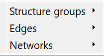
the Structure groups menu item is only available if the structure file contains line structures with the VORF attribute.
Watercourse sections can be edited via the menu item Edges:
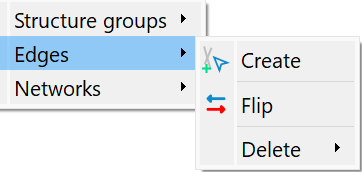
When creating edges, for example, lateral branches or diversions of a watercourse section can be added along element edges.
When flipping a water edge, the flow direction is reversed and the affected sections of the watercourse are separated from each other (splitting the group) or merged together again.
Individual edges (Pick...) or areas (Polygon) can be deleted using Delete.
The Networks menu item is only active if watercourse systems (VINZ index table) are already present in the model file.
Creation of watercourse systems
If there are watercourse water level structures, the next menu item is active

and the watercourse structures can be prepared. The following input window appears
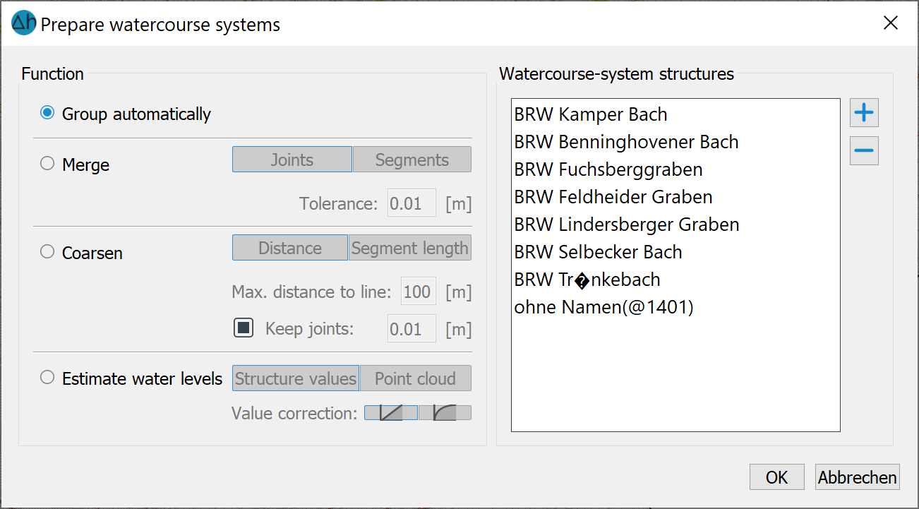
Firstly, the desired structures are selected from the structure file using the plus symbol.
The structures can be edited using the following functions:
Group automatically
The automatic grouping tool is used to summarise related structure segments in individual groups. When used in flow systems, care should be taken to ensure that only line structures that are part of the flow system are included in the model. Related structure groups are highlighted in colour.
Merge: joints - segments
Points that lie within the user-defined tolerance distance are merged. This is particularly important for subsequent grouping.
The tool recognises flow segments that can be safely combined without changing the geometric interpretation of the system. This tool is useful in a number of scenarios, for example when the river system is imported from shape-files, which results in individual rivers being represented by numerous small segments that could easily accumulate into thousands of structures in large models.
Coarsen
Coarsening is useful when a coarser structure can be displayed with fewer points without losing essential information. With the coarsening tool, users can coarsen structures based on two different criteria.
The first method is based on the perpendicular distance between each point within the structure and the line formed by connecting the two immediately surrounding points. The maximum distance can be specified via the corresponding field in the dialogue. Points with a shorter distance than the specified value are recognised and removed by the algorithm.
The second method is based on the length of each segment in the structure. After the correction, the respective structure consists of segments whose lengths are greater than or equal to the value specified by the user. All points in between are removed.
The correct choice of coarsening method and parameters is crucial for achieving suitable results.
Estimate water levels
This function can be used to automatically calculate and correct water levels and determine flow directions of river systems in the model. The algorithm uses a robust combination of geometric and geological analyses for this purpose. The result of this tool depends heavily on the correctness and accuracy of the input data provided (preferably a high resolution digital terrain model).
After the watercourse preparation and automatic grouping, the structure groups can be managed. An input window appears for displaying/cancelling/assigning structure groups:
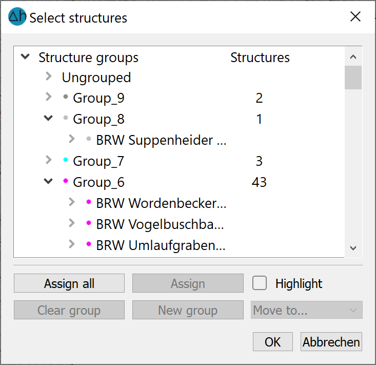
In the dialogue are:
the structural groups summarised in individual watercourse systems, and
the number of structures not belonging to water systems
shown.
Watercourse systems do not include point or area structures or line structures that are not assigned the VORF attribute. If structure groups exist, they can be assigned either "all" or "individually". You can delete individual groups via "Clear group" and create new groups via "New group".
After assignment, you can display all assigned watercourse systems via View → Watercourse system.
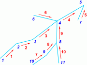
The following diagrams show a comparison of watercourse systems that are not prepared and grouped (left) and those that are geometrically processed and grouped (right).
 |
 |
|
No geometric processing and grouping |
Geometric processing and grouping |
The same colours show water systems that form a singular system due to their connection and the bed or flow gradient.
Processing of existing watercourse systems
Further settings can now be made via the menu item Networks:
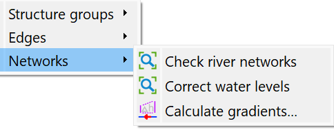
Check river networks
Here, a check is carried out on the correctness of the flow direction of the water systems. Due to the conservation of mass, exactly one stream always flows away from each water node, and any number may flow into a water node..
Correct water levels
The following dialog appears:
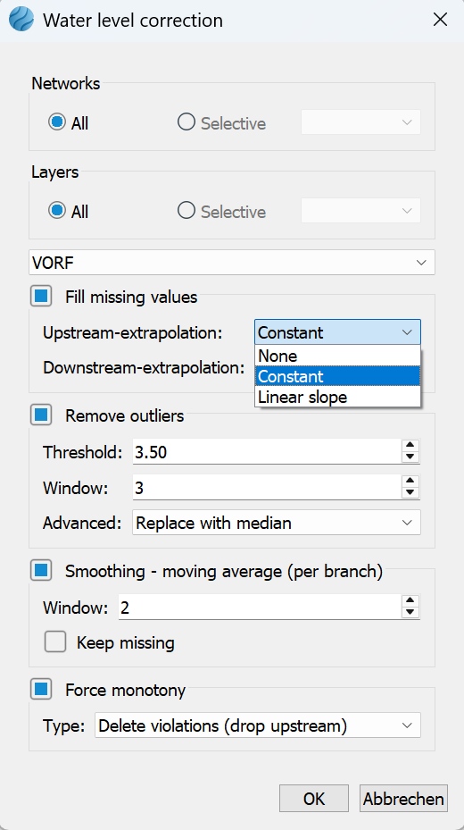
Missing water levels can be added or incorrect values can be corrected based on this dialog.
The selection of "constant" upstream or downstream extrapolation allows the mapping of weirs in a watercourse. In this case, the missing water levels are filled with the same value until the next node with a value is reached.
Example:
By choosing "constant" the values "10, missing, missing, 13" are extrapolated in the values "10, 10, 10, 13". Choosing "linear" results in the values "10, 11, 12, 13", taking the edge length into account.
The term "window" defines the number of nodes to be considered in each case.
Normally, the preset values in the dialog are completely sufficient for a water level correction.
Calculate gradients
After selecting this function, a dialogue window appears in which the user can choose whether the slope gradient is calculated from the receiving water potential heads or the top edge of the terrain.
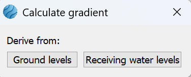
The VGRD attribute is calculated for all watercourse systems (unit: per thousand) and stored in the model file after saving the model. The gradient (corresponds to the bed slope) results from the ratio of the difference between the upper edges of the terrain or watercourse water level to the distance of the neighbouring nodes along the affected element edge.
 Transient
Stand: 22.05.2026 | 