Attribute: MARK [-] (node- or element-wise)
The MARK attribute can be used to add symbols to nodes or element centres, or to connect them with a line. Markings on element centres can only be assigned by editing the *.net file or the *.3d file.
The MARK attribute must be defined using an integer number, only the integer part of the provided value is understood by the programme. The sign of the assigned integers indicates what kind of geometries are listed:
Integer value < 0: Negative integers indicate that the provided list contains only element numbers, and the markings are placed in the centres of the listed elements.
Integer value > 0: Positive integers indicate that the provided list only contains node numbers.
With connecting lines, the points are connected in the order in which they were entered. A completed list of numbers represents a line.
Value +/-1  Square at a node / in the centre of an element (
 )
)
Value +/-2 Octagon at a node / in the centre of an element ( )
)
Value +/-3 Triangle at a node / in the centre of an element ( )
)
Value +/-4. Cross at a node / in the centre of an element ( )
)
Value +/-10 Connecting marking line between nodes / elements
Value /-(100+X) PLX marker type X at a node / in the centre of an element
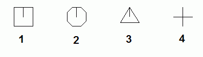
Representation of the MARK attribute with the values 1, 2, 3 or 4
The other markers (36 different markers in total) can be displayed with the attribute value MARK = 100+X):
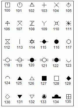
Possible marker symbols in SPRING
The node or element markers can be changed directly in SPRING. To do this, the appropriate toolbar must first be displayed via the menu item View Toolbars Attribute. By means of the Assign attribute directly toolbar button and selecting MARK as the active attribute, all possible marker types are displayed in the resulting dialog box and can be assigned directly to nodes. Alternatively, via the Edit node toolbar buttons (One of these buttons functions by selecting the node, the other button requires you to specify a node number) a dialog box can be used to change the assigned MARK number of the node.
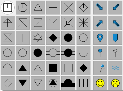
Current marker selection
Assignment table of the numbers of the coloured markers:
|
44 |
45 |
|
47 |
46 |
|
36 |
37 |
|
39 |
38 |
|
42 |
43 |
|
40 |
41 |
After activating the Assign object properties button and selecting the node, the marker is assigned to the node or an existing marker is changed
Example:
MARKINGS
-3.0 111- 114, 14
133.0 99
1.0 23- 25
10.01 23- 25, 33
10.02 99, 88, 75
Elements 14, 111, 112, 113 and 114 are marked with a triangle. A marker of type 33 (filled triangle in a circle) is plotted at node 99. Nodes 23, 24 and 25 are labelled with a square and also connected with a line. A connecting line is also drawn through nodes 99, 88 and 75.
Stand: 06.05.2025 | 