A path line is the line resulting from following the movement of a single water particle over a certain flow time t. It is computed by following the flow path of an imaginary water particle through integration of the flow field. Path lines are calculated using the field velocity va, but not the Darcy velocity vf. The field velocity is the actual interstitial velocity referring to the mesh flow area. It is obtained by:
with
Two factors strongly influence the accuracy of path lines:

First, since each element has a constant calculated velocity as a result of the linear shape function for potential heads, areas with changing potential gradients require a fine discretization.

Second, the transition from one element to the next must be smooth.
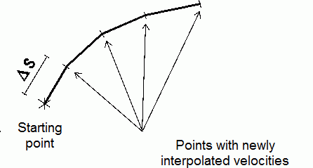
To achieve this, the path line is first followed a certain distance (s) with the initial velocity; then in the next step, a new velocity is interpolated and the line is continued. The distances chosen depend on the homogeneity of the flow field.

Computing a path line
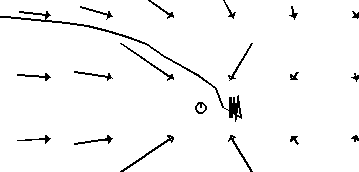
Exfiltration wells are difficult points for computing a path line. They must be considered as a secondary condition. Otherwise, the changing flow directions result in zigzag lines:

Computed path lines at a well without any secondary condition
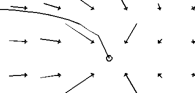
Better results are obtained by checking whether the computed path line has reached the “capture radius” of the well. Then the path line will end directly at the exfiltration node:

Computed path lines at a well with "capture radius” depending on the exfiltration rate and the distance
If one of the following criteria is fulfilled, the computing of the path line ends:

the defined time or distance is reached,

the outer boundary of the model or a free water surface is reached,

the path line is captured by an exfiltration well,

the distance between two computed path line points is less than the defined limit.
Die Umsetzung bzw. die erforderlichen Eingaben in SPRING werden im Kapitel
The implementation and the necessary entries in SPRING are described in chapter "Calculating and plotting pathlines".
The starting point of a path line can be a node, the centre of an element or any point with the coordinates x, y, (z). The direction for following the path line is either the flow direction or the direction opposite to the flow. The latter one is useful for determining the protection area around a well (e. g. 50-days-zone). The plot generation can mark time intervals along the path lines. Finally, isochrones can be manually constructed with them.
The computation of transient path lines differs from the above procedure only in that the velocity field changes continually. Therefore, in addition to the distance s, the particle travel time t must be checked. It cannot be greater than the time-step length T in the transient flow calculation.
 Calculating and plotting path lines
