Call via: SPRING  Calculation
  Model checking…
This calculation module checks the input data and prepares them for the finite element calculation. It reads the *.net-file and, if applicable, the *.3d-file and other additional files (if provided). The program checks if the data are complete and (optionally) if they are plausible. All identified errors are recorded. Furthermore, a band-width optimization which is specialised for 3D models is carried out. The superfluous nodes and elements resulting from partial layers are eliminated. The prepared data are output into binary files for the subsequent calculations.
In the model checking internal calculations may be performed and values of input attributes are subsequently assigned.
If the *.net-file contains data for terrain settings as a result of subsurface mining (BERG), they will be considered automatically in the calculation. Hence the values are subtracted from the following data:

Ground level (GELA)

Lower boundaries (UNTE)

Upper boundaries (OBER)

Z-coordinates (ZKOR in 3D model)

Water course levels (VORF)
Terrain settings enlarge the water filled thickness.
Example:

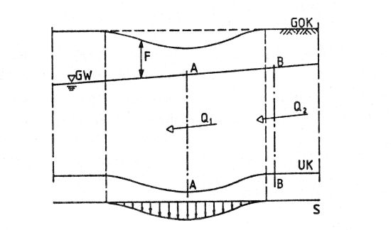
Section of an aqifer influenced by subsidences
From section A – A to section B – B the continuity condition has to be satisfied (Q1 = Q2). In areas influenced by subsidences the water filled thickness is reduced so the flow condition changes. The setting of the ground level decreases the distance ground level – ground water level (F).
In order to keep the size of the input file as small as possible, in a 3D model the data of the higher layers are automatically assigned to the deeper layers, in case there are no data for these layers in the *.3d file. The following attributes are automatically assigned:

Initial potential heads (EICH)

Permeabilities (KWER, KWEV, KFVH)

Limitation of the permeabilities (KMIN, KMAX)

Dispersivities (DISP)

Porosities (PORO)

Storage coefficients (SPEI, KSPE)

Initial concentrations (AKON)

Anisotropic conductivities (Z-KA)

Compressibility of the entire system (KOMP)
The model checking makes it possible to use other modules in spite of errors in the input files. The errors are divided into possible mesh errors (no. > 0) and possible data errors (no. > 0). For instance, in case of data errors the mesh can be plotted (File  Plot generation) or data can be interpolated (Calculation
  Interpolation). Absolutely necessary are the coordinates of the nodes and the element description.
Unknown data types are skipped, resulting in a warning being generated and recorded. The defined identifications KKKK for any node wise data, and EEEE for any element wise data, are useful for e.g. possible calculations between different input data or comparisons with results using the plot generation.
