Beside the measured values at groundwater observation wells it is essential to take boundary conditions into account when interpolating a groundwater contour map. There is to say fixed potential heads, boundary inflow/outflow at nodes, receiving water courses, leakage or equal unknown potential heads. Especially for the automatic calibration it is important to consider the hydrogeological circumstances in the investigation area
The actual net file should be copied for this interpolation, because some of the used attributes make sense only in this algorithm.
On our homepage http://spring.delta-h.de is a zip archive available for download under Download & Support at Tutorial (EN) ( ) containing sample files. The directory Tut_Intpol_GwGl contains a mesh file and a file with measured groundwater levels, which should be used in the interpolation of a groundwater contour map.
The following processing steps are carried out in order to create an interpolated groundwater contour map.
The interpolation is performed after running the model checking when choosing the interpolation type groundwater contour map and activating the button "additional interpolation points".
A receiving water course is considered by assigning the attribute LEKN (value between 0.0 and 1.0) to the corresponding nodes.
LEKN = 0.0 means, there is no groundwater contact.
LEKN = 1.0 means, there is full groundwater contact.
Existing leakage coefficients (LERA or LEKN) should be deleted, otherwise this receiving water course is not taken into account in the interpolation.
In the example the nodes 204 - 215 of the receiving water course get the value LEKN= 0.9 via Attributes  Assign
  Direct. The nodes of the headwater which is supposed to have no groundwater contact get the value LEKN = 0.0.
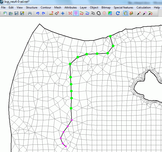
Assigned LEKN attributes (green = 0.9, pink = 0.0)
If the boundary nodes without inflow should be considered in the interpolation the attribute KNOT = 0.0 has to be assigned to the corresponding nodes.
The attribute KNOT = 0.0 is assigned to the western and southern boundary nodes.
After saving the project and running the model checking you can now activate the check boxes “receiving waters with leakage” and “boundaries without flow in or out” when you have activated the check box “additional interpolation points” before.
The numbers 1 to 4 behind the chosen attributes define the priority of how these attributes are considered in the interpolation:
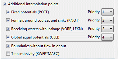
After selecting the "File with interpolation data" ("gwmesspkte_int_gwgl.txt") the calculation can be started.
The following figure shows the groundwater contour map of an interpolation with (red) and without (blue, only the measured data in the file "gwmesspkte.txt" are considered) considering the additional interpolation points.
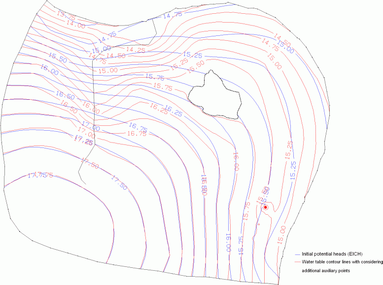
Bild: Comparison of the contour lines after interpolation with (red) and without (blue) considering additional interpolation points
Especially in the area around the lake you can see that considering the equal unknown potential heads (GLEI) prevent the water table contour lines from intersecting the lake surface. The following figure shows in detail how taking the receiving water course level into account has effects on the course of the equal value lines: now the contact between the receiving water course and the groundwater level is visible!
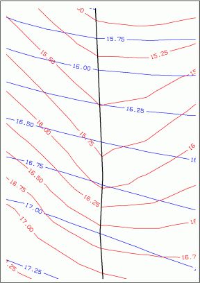
Bild: Visible groundwater contact of the receiving water course by considering the leakage interaction in the interpolation
The calculated potential heads are assigned to the attribute EICH (initial potential heads) with Attributes  Import data/computation results...
Attention: For the following flow computation it is recommended to delete the attribute KNOT = 0.0 and to reassign the leakage attributes (LERA). Values between 0 and 1 make only sense for the interpolation and not for the flow computation!
The calculated additional auxiliary points are saved in the file "stuetzTMP.txt". If you join this file with the file including the measured data (here: "gwmesspkte.txt") you get a file with all required interpolation points.
Beside the effects of the parameters shown above sometimes the consideration of other parameters is advisable:
With the help of the attribute KKKK it is possible to keep a minimum depth to the water table. The prescribed distance between groundwater table and the ground level is assigned to the attribute KKKK (in meters). Is the calculated depth to the groundwater table lower than the required value of KKKK, the calculated depth is adjusted to this value.
To consider the influence of the permeability (KWER) and the thickness (MAEC) of the water saturated zone a transmissivity-weighted interpolation between the groundwater observation wells is required. Necessary for this procedure is a global definition of the attributes KWER and MAEC. The transmissivity of the elements, intersected by an assumed line between two adjoining observation wells, is calculated and their hydraulic gradient is weighted.
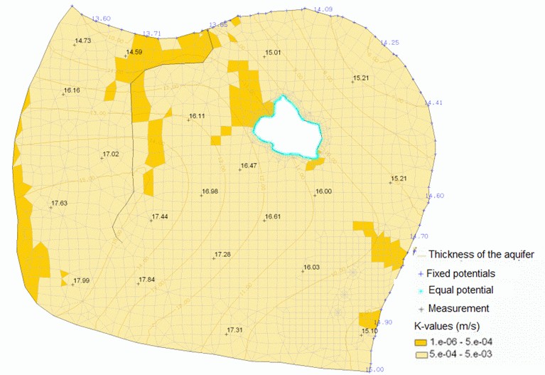
Figuring the initial model data
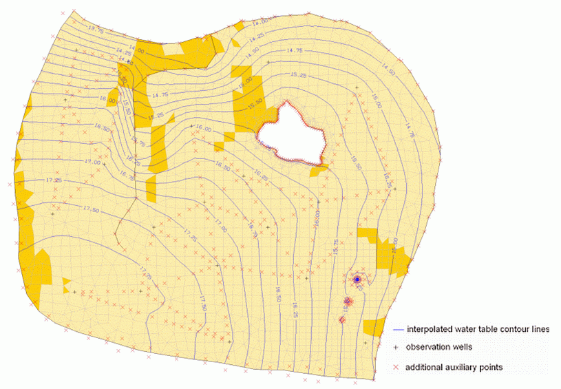
Groundwater contour map after consideration of different hydrogeological parameters
A transmissivity-weighted interpolation takes place only when there are more than three FE elements between two adjoining observation wells or when the transmissivity varies more than 10 %.
Considering the transmissivity in the interpolation algorithm requires detailed knowledge about the permeability and water saturated thickness of the system before the calibration. This functionality should only be used under the following circumstances:

only a few groundwater observation wells

a coarse mesh discretization
 Interpolation to a Node Track under considering the Floodplains
