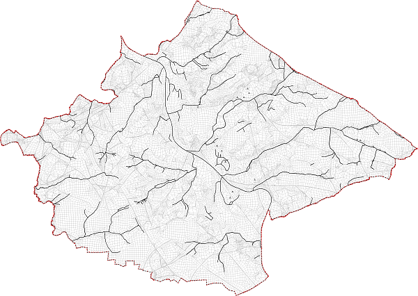
In the first step, the model nodes that lie within the partial model edge are deleted from the overall model. The following figure Fig. 23 shows the area of the partial model before importing it into the overall model.

Partial model area before importing it into the overall model
Along the outer edge of this model, the nodes and elements from the existing overall model are removed (Mesh  Nodes
Nodes  Delete
  All inside selected structures or Mesh
  Element
  Delete
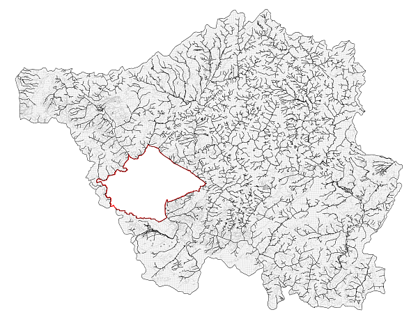
  All inside selected structures). The following figure Fig. 24 shows the remaining mesh of the overall model.

Partial model area, removed from the overall model (red)
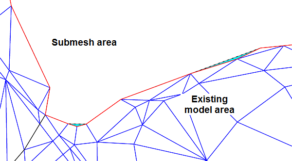
In case of concave edge gradients it happens that elements remain in the area of the partial model because their corner nodes lie on the model edge (Fig. 25cyan highlighted elements that are outside the red border line). These elements have to be removed manually.

Elements, which are not automatically removed
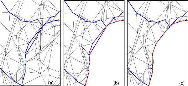
A second step is to examine whether linear data structures (e.g., water courses) intersect the model edge multiple times. If this is the case, the lines have to be separated between the point at which the line leaves the remaining model area and the point at which the line runs again into the model area.
The following figure Fig. 26 shows such a situation. The image (a) represents the initial situation in the overall model. In image (b) the mesh along the broken red line was cut. In this case a blue line runs out of the remaining mesh and at another point back inside the mesh. The locations where such a situation occurs, have to be identified and must be adjusted by separating the lines (c).
This step is not only required for a correct presentation (e.g. markings), but also for a proper consideration of line-related leakage boundary conditions.

Correction of line data
