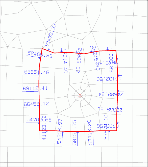
To calculate the inflow to an abstraction well, a closed control line is placed around a well. In the following example, a well (KNOT) with a withdrawal of -800000.0 m³/year is defined in the centre of the model.
The control line (red) lies within a radius of approx. 400 m around the extraction well. The area of the control volume (= circumscribed area of the control line) is 560505 m², which leads to a groundwater recharge (FLAE = 0.200 m³/m²/year) in this area of 112101 m³/year. The FE mesh looks as follows in the initial state in the area of the well:

Initial state of the well calculation
After a flow calculation with the SITRA module (partial saturation, 5 iterations), an inflow volume of 702533 m³/year into the control volume is obtained (output file of the flow calculation out.*). Together with the groundwater recharge volume, this results in an inflow of 814634 m³/year, which corresponds to a percentage deviation of 1.8 %. The percentage deviation can be further reduced by refining the mesh.
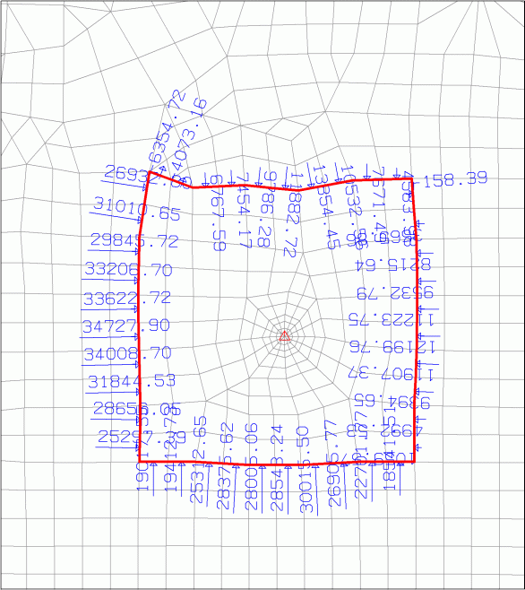
After an area-by-area refinement by the control volume, the inflow volume is calculated as 112101 + 690024 = 802125 m³/year. This means that the deviation has already been reduced to 0.3 %.

Simple mesh refinement in the investigation area
 Use of control lines to determine bank filtration volume of a large main receiving watercourse (POTE)