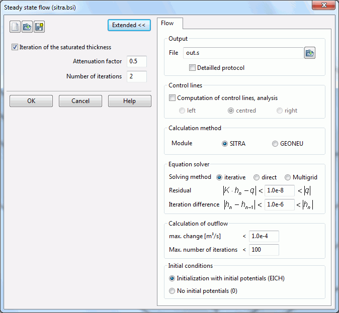
By activating the "Extended" button other parameters can be set. First, the inputs of the module SITRA are described:

Output
The name of the output file is entered, default is the name out.s in the module SITRA and out.g in the module GEONEU.
In a detailed protocol (only SITRA) the intermediate time steps of a transient calculation are stored as well as the mass balances (for each node), calculated volumes of control lines (for each node), calculated potentials, concentrations or temperatures, saturations (by a saturated / unsaturated calculation), and velocities.
Control lines
(only if the attribute KONT is defined in the model file)
After checking the box the computation of the control lines is done. For each segment of the control line, a velocity is required. The velocity can be determined as the mean value over the two adjacent elements. Otherwise, the velocity of the left or the right element is chosen.
Calculation method
Possible are the modules GEONEU and SITRA. Default is the calculation with SITRA.
Equation solver
As an equation solver either the iterative PCG solver, the direct Cholesky solver (LU decomposition) or an algebraic multigrid solver can be selected. For meshes of about 500 nodes or more, you should always choose the iterative one, because it is much faster. The error due to the iterative solution is always much smaller (less than 3%) than the other errors (e.g. measurement error). This can be verified with the help of the mass balance printed to the output file. The multigrid solver is particularly recommended for models with large local differences in the permeabilities.

Iterative PCG solver: General CG method with preconditioning (Preconditioned Conjugate Gradient Solver) with block-SSOR relaxation (Symmetric Successive Over Relaxation Method)

Direct Cholesky solver: Gaussian elimination method

Multigrid solver: CG method with preconditioning by multigrid methods
Residual and iteration difference (iterative and multigrid solver only)
The basis of the iterative solution method is the boundary value problem defined as variational problem from which by discretization a quadratic function F (v) results whose minimum gives the desired solution. The partial differentiation of F produces the known symmetric and positive definite system of equations as a necessary condition for the minimization:
In the following the exact solution vector is named h* is named, now to be determined by an iterative process. With h as so-called trial vector, the quadratic function can be written as:

Or in index notation:

The partial differentiation to hi leads to:

δF / δhi is the i-th component of the gradient or for the residual vector g for the trial vector h,

Which now will be lead toward the value zero within the iterative process (or in this case: 1.0e-08).
The iteration process that leads the residual vector g to zero, contains a systematic correction of a sequence of approximation vectors h in the following form:
Therein the trial vector hi of the i-th iteration is improved to the new approximation vector hi+1 using the iteration vector di and a scalar step size ηi.. The vector di gives the direction of the relaxation which is oriented to the minimum of the function.
The iteration process is terminated when a pre-set convergence limit (iteration difference) ε is reached or exceeded, so that the accuracy of the result to be achieved is determined by the choice of this convergence measure (iteration difference) ε.
The various vectors which are involved in determining the termination criterion are related by forming their Euclidean norm. This results in the following termination criterion:

Calculation of outflow
The input data for the flow calculation is described in detail in chapter: Input for water course system calculation .
Initial conditions
When selecting the module SITRA, the initial conditions for the steady state flow can additionally be determined. It is possible, to take over the initial potential heads from the attribute EICH or from the null-file, or the initial potentials can be set to 0.
 Input for water course system calculation
