Attribute: MARK [-]
With the attribute MARK, individual nodes or element centers are provided with symbols or connected by a line. Markings on element centers can be assigned only by editing the *.net file or the file *.3d. The entered value has to be negative.
The definition of markings requires an integer number. Hence follows that only the integer part of the value is interpreted. The identification numbers have the following meaning:
Value < 0: the list of numbers contains only element numbers, the markings are placed into the element centre.
Value > 0: the list of numbers contains only node numbers.
Single nodes or element centres can be marked by a symbol or connected by a line.
The points are connected according to the order in the input file. A closed list of numbers represents one line.
 Quadrangle at a node / in an element centre (
 )
) Octagon at a node / in an element centre (
 )
) Triangle at a node / in an element centre (
 )
)  Cross at a node / in an element centre (
 )
) connection line between nodes / elements
  PLX marker type X at a node / in an element centre
Of the 36 possible marker symbols only the first 4 are shown directly with a value MARK = 1, 2, 3 or 4 in the user interface or after the plot generation (see figure below):

Marking symbols with the value MARK = 1, 2, 3 or 4
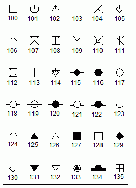
The others have to have the value MARK = 100+X (see figure below):

Possible markings in SPRING
The node or element markers can be changed directly in SPRING. For this the appropriate toolbar first has to be displayed by the menu item View  Toolbars
  Object attributes. By activating the marker selection all possible types of markers appear from which the desired type is selected. After activating the button Assign object attributes and selecting the appropriate node the marker is assigned to the node or an existing marker at the node is changed.
Example:
MARKINGS
-3.0 111- 114, 14
133.0 99
1.0 23- 25
10.01 23- 25, 33
10.02 99, 88, 75
Elements 111, 112, 113, 114, 14 are marked by a triangle. Node 99 is marked by a polymarker of type 33 (filled triangle in a circle). Nodes 23, 24 and 25 are marked by a quadrangle and connected by a line. Nodes 99, 88 and 75 are also connected by a line.
