Agreements
A mine is at the beginning a total unsaturated 3D area which is totally or in parts under the compound surface. In addition:

The nodes which belong to the mine are indicated by explicit zone numbers (data type GRUB, numbers > 0).

For all FE-mesh-nodes of the considered mine where an inflow is possible the boundary conditions must be defined as "free off seepage" (data type SICK). If there are drainages for the mine pumping facilities which drain into the mine the affected nodes can get the boundary condition "water course level and leakage", additional the node can be supplied with the attribute for the zone number of the mine (data type GRUB, see above).

For the time t=t0 is no water in the mine located (no initial volume).

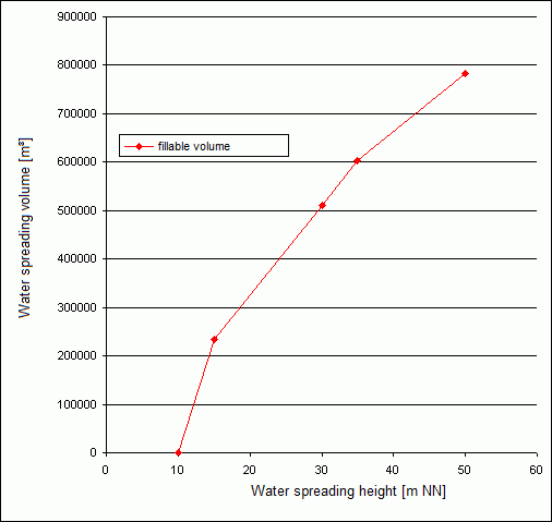
For a transient flow calculation a steady ascending curve is available for the description of the ratio between water spreading volume (m³/s) and the water spreading height (m NN).

Temporal course of the water spreading in a mine
After each time step t = ti the flow rate is balanced which inflow happens from time t = t0 to time t = ti into the mine. The volume is composed of the inflow considered at the point in time t = ti - ti-1 on the mine nodes and the spreading volume until to the point in time t = ti-1. If there are drainages in the mine and marked in the way which is described above the inflow of the drainage will be added to the volume in the cavity.
With the relationship between the water spreading volume and the water spreading height the resulting water spreading height h(Vi) can be calculated at the considered point in time from the volume V(ti).

For each node with the boundary condition "free off seepage" the vertical location z estimates if the node lies over the free surface h(Vi). For a node lying under the free surface the boundary condition "free infiltration boundary" is changed into "fixed potential" or alternatively in "water course with leakage" with the height h(Vi). For all other nodes with the boundary condition "fixed potential" or "water course with leakage" the height h(Vi) will be updated.
This procedure guarantees that the mass which is removed out of the model by the boundary conditions "free off seepage" will be completely added back through the definition of fixed potentials or water course nodes. So the mass balance in the model is ensured.
If the "off seepage nodes" change in "potential nodes" or in the damped boundary condition "water course node" is defined through flow parameters.

When choosing the "water course node" entering a leakage value for the nodes (LEKN) is required.
Pile-up of a mine
If all nodes of a mine have at one point in time the boundary condition "confirmed potential" the mine considered to be overflown. In this case all (potential-) boundary conditions are "deactivated" so that the mine will be considered in the flow calculation as a totally saturated subarea of the aquifer.
Lowering device of the water level in a mine
If the water level drops in the minethe nodes now lying over the free surface will change (inverted equal to the water spreading procedure) from the boundary condition "confirms potential" back to the boundary condition "free off seepage".
If the water level drops down after a pile-up in the mine all mine nodes get back their originally boundary conditions. That means, when the water volume in the mine is no more filling it up the mine nodes which lie below the surface get the boundary condition "confirmed potential" and the nodes lying above the surface get the boundary condition "free off seepage", always considering the relationship between water spreading volume and water spreading height.
Limitation of the water level
If for a mine a maximum water level is defined and achieved the volume which guarantees keeping the water on that level in each time step is removed from the model. The calculation of the shrinking volume is based on the water spreading volume-water spreading height-relationship. Thus the water level must be located in the codomain of the function.
A temporal changing of the water level is always possible using the transient input file. The data type is described through HMAX. The values correspond to the zone numbers of the mine.
Addition of water from outside the model
When water is added to the mine from outside the model during the flooding phase this can be defined as a flow rate. If such a volume is defined for a time step it is considered in the calculation of the water spreading height using the water spreading volume-water spreading height-relationship. A mathematically positive volume defines a water supply to the mine and a negative volume defines a water removal from the mine.
A temporal changing of the water supply is always possible using the transient input file. The type of data is described with MENG. The values correspond to the zone numbers of the mine (see "Limitation of the water level").
Definition of the flooding parameters in SPRING
First of all each FE-mesh-nodes which describe a mine get an explicit number at the data type GRUB before a flooding simulation with the above described method can be executed. In the following procedure this number is used as the zone number (X) of the mine.
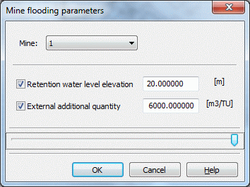
If nodes indicate a mine the further flooding parameters "water level" and "addition volume" can be defined with the menu Attributes  Special features
  Flooding parameters (GRUB). Should a set parameter be changed the entry in the relevant field has to be deleted (field remained blank).

Definition of the water spreading volume - water spreading height-relationship
For each mine a continuous function must be defined which describes the dependence on the spreading volume and the water level in the mine:

The function should be defined over the total interval of the water spreading procedure, that means, for all appearing values of the volume and the height during the simulation.
For the flooding calculation the water spreading volume-water spreading height-relationship for each mine must be prepared in the format CSV (separators disconnected) and placed in the working directory. The files have to be named after "grubeX.hv" where "X" is the corresponding zone number. This file is read automatically by the calculation module.
10.0,0.0
15.0,234900.0
30.0,511600.0
35.0,602800.0
50.0,783000.0
Results
Beside the known results (potentials, free surface, hydrograph, etc.) from the transient flow calculation SPRING creates for each cavity during the flooding simulation a volume hydrograph which describes for each time step the actual water spreading volume and by definition of the water level a volume hydrograph of the shrinking volume. Additionally the volumes for each boundary condition for each time step are saved. The file is created with the name "gruben.csv" (separators disconnected) in the working directory.
 Example of a realization in SPRING
