After opening the existing project in SPRING you define the boundary of the 3D area with Mesh  3D
3D  3D-Boundary
  Mesh-Boundary = 3D-Boundary. With View
  More Windows
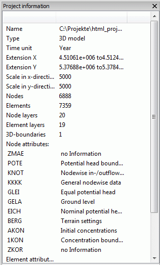
  Project information you see that the model type has changed to “3D-model”.

Project information
Next you have to arrange the new layers with Mesh  3D
3D  New layer arrangement… in the following dialog box:
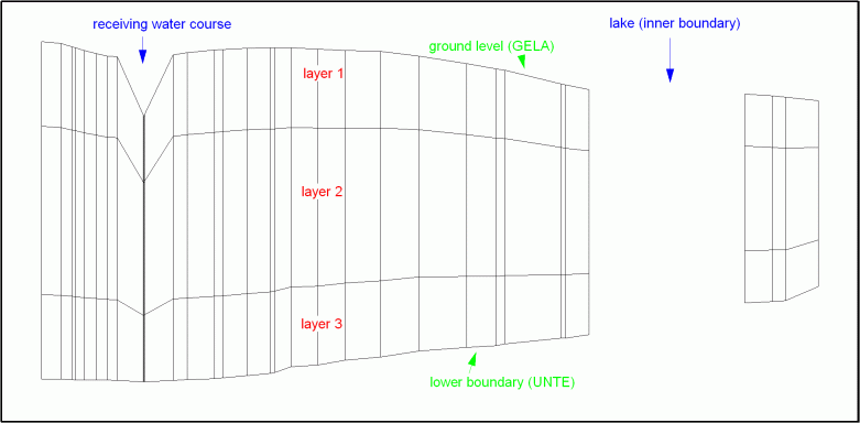
If you have considered which and how much element layers are necessary (e.g. dependend on exploratory drillings) these numbers are entered in the input field. They have the following meaning:

The number of the figures (here: 3) defines the number of new element layers.

The sum of digits of the numbers (here: 1+2+1=4) defines the partial thickness of each element layer. That means, the entire thickness (= - UNTE) is divided by 4 and multiplicated with the given numbers. So the first element layer gets a thickness of 1/4th of the entire thickness, the second gets a thickness of 2/4th of the entire thickness and the third gets a thickness of 1/4th of the entire thickness.
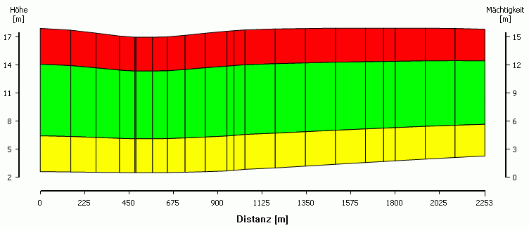
The following vertical section shows the proportions of each generated layer:

Vertical section of the new 3D model (hundredfold super-elevation in Y-direction)
It is possible to create a user-defined section at every time with View  Vertical section: You select two points by pressing the left mouse button and the vertical section appears in an additional window.
This feature is independent of the model type.

User-defined vertical section through a 3D-model
The layers of the 3D-model can be visualised with View  More windows
  3D-View. An additional window opens, in which you can move the model in all directions by pressing the left mouse button:
After saving the project you get the files "schulung_3d.net" and "schulung_3d.3d". You can download them from our homepage for further proceedings in the next chapter: "schulung_3d.zip"
For a common flow computation it is sufficient to assign the permeability KWER to the elements of the new layers with Attributes  Assign
  direct. For difficult hydrogeological conditions a calibration for each layer is requested and other necessary attributes have to be assigned to the generated nodes and elements (e.g. saturation parameters or impermeable layers, etc.).
 3D-Enlargement by the definition of Z-coordinates (ZKOR)
