For an easy overview, the marker "120" (typical well marker) is assigned to the pumping well as follows:
The withdrawal nodes can be displayed via View  Show attributes
  .../Values
  KNOT and assigned the corresponding mark via Attributes
  Assign
  Direct: MARK = 120.
For the subsequent flow calculation, the groundwater recharge (FLAE) and the permeabilities still have to be assigned. These data types can be assigned globally to all elements by clicking on Attributes  Assign
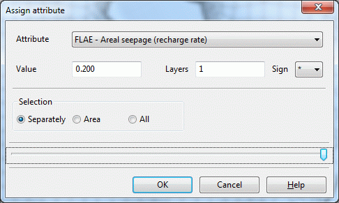
  Direct. In the example, the groundwater recharge for the entire area is set to FLAE = 0.200 with the added character " * ", which corresponds to a recharge rate of 0.200 m3/m2/time unit or 200 mm/year.

Assigning attributes directly
The same is now done for the definition of the permeability values (KWER) of the model area, but without additional character in the 15th/16th column. The starting K values before starting calibration are set to 0.00005 m/s. In addition, an upper (KMAX = 0.002 m/s) and a lower (KMIN = 0.000001 m/s) limit for calibration are introduced for the K values, which must also be assigned to all elements.
The assigned marks can be displayed via View  Markings, or the corresponding button (
 ) can be pressed.
The mesh generated up to this point, including the structure data file, was already downloaded from our homepage in the directory: ".../Tutorial_bsp_files/Tutorial_2D_bsp_files/s3_schritt3_3.zip“.
Since all data required for calibration are now available, the calibration procedure is illustrated in more detail in step 4: Calibration of a groundwater model.
